MLC 62 Series • Hardware Setup
Hardware Setup, cont’d
2-14
3. Plug the 3-pin connector into the MLC's 3-pole Relays port
connector.
To define the operation of a relay and associate it with a button
or a digital input, use the configuration software. (Refer to the
configuration software help for setup procedures.)
Wiring the IR/S port
You can connect a display device, switcher, or one or two IR
emitters to the IR/S port. The port allows a serial or an IR
connection. (In the configuration software, this port is called
the "Serial Port" or the "IR Port", depending on how it was
configured.)
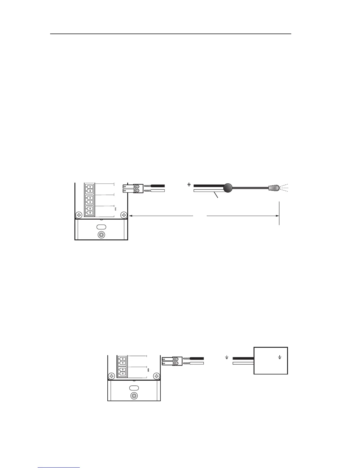
The illustration below shows how to wire the IR/S port for IR
control via an IR emitter.
MLC 62 RS D
Rear Panel
GROUND
GROUND
+12 VDC
Unidirectional IR Output
via White Striped Wire
50'
(15 m)
Ground ( )
IR Signal
IR Emitter
Connecting an IR emitter to the IR/S port of an
MLC 62 RS D
Wiring the RS-232 port
You can connect a display device or switcher to this serial port
to control the output device via RS-232. (In the configuration
software, this port is called the "Display Port".)
N
On all models, the Tx pin on the MLC is connected to the
Rx pin on the output device.
MLC 62 RS D
Rear Panel