MLC 62 Series • Hardware Setup
2-15
Refer to the communication sheets for your device drivers for
information on compatible baud rates and cabling type and
distance. Refer to the configuration software's help file for
instructions for accessing the communication sheets and to
download the device drivers.
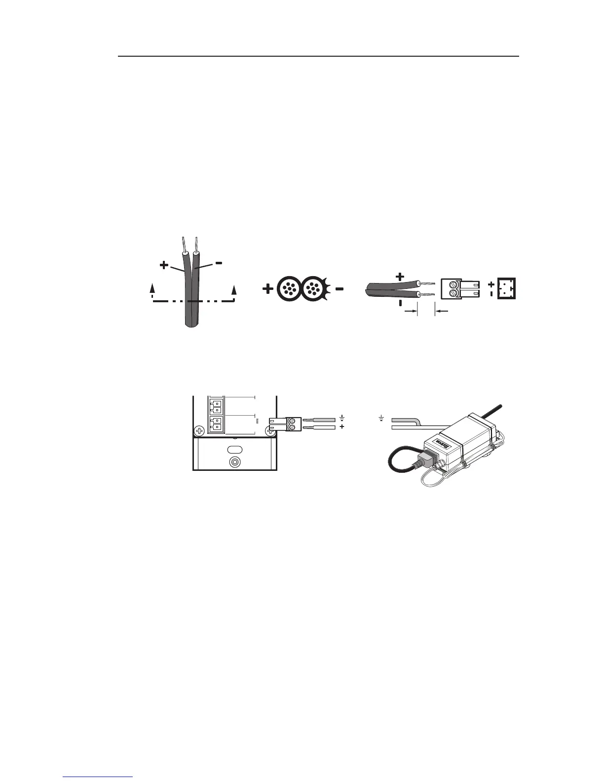
Connecting power to the MLC 62
Connect the provided 12 VDC, 1 A power supply to the MLC 62
as follows:
a. Wire one of the supplied 2-pin captive screw connectors as
shown below:
SECTION A–A
Ridges
Smooth
Power Supply
Output Cord
A A
3/16”
(5 mm) Max.
b. Plug the connector into the rear panel PWR connector.
External
Power Supply
(12 VDC)
MLC 62 RS D
Rear Panel