Digital Brushless AC servo drive system - Ref.0707 MCS- 39/92
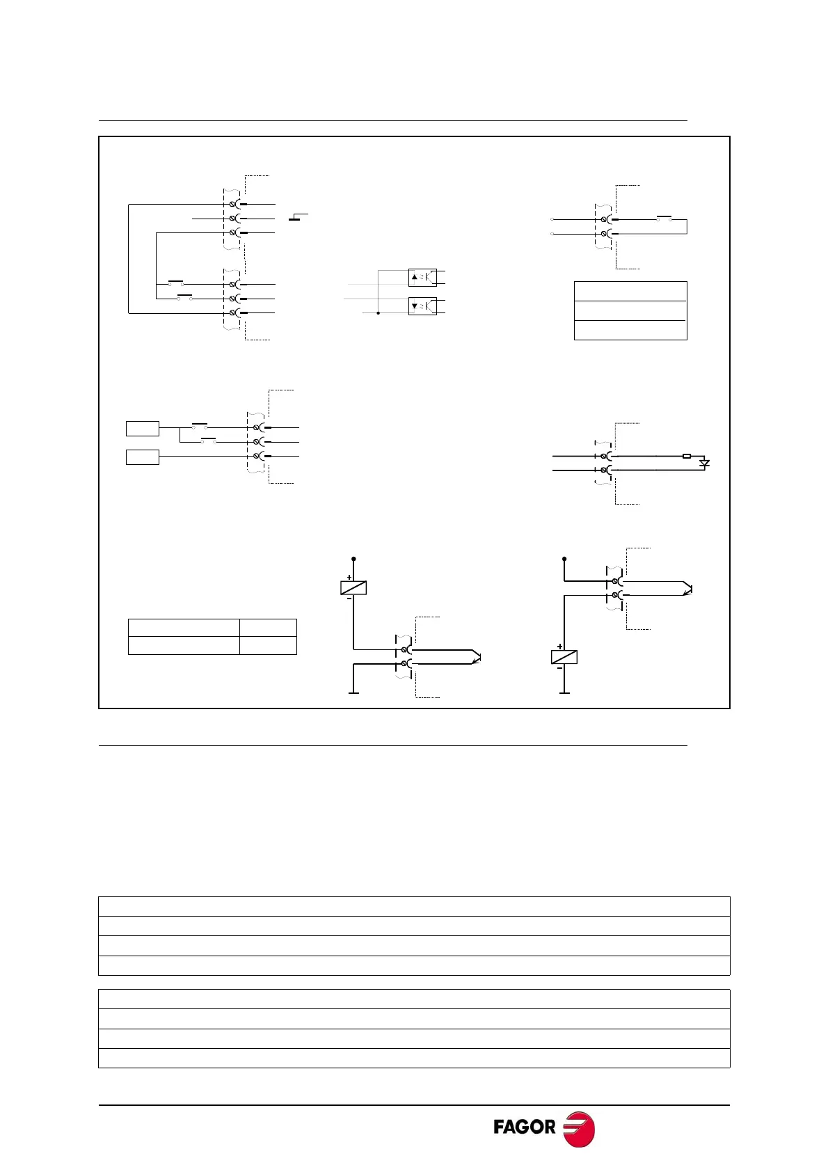
Connection of the monitoring and control signals
Encoder feedback connection
The signals generated by the encoder are taken to the ENCODER INPUT of the MCS
drive. The MCS amplifies these signals and may divide their frequency. The division
factor is given by the values of parameter EP1 and the sequence between A and B by
parameter EP3. The MCS drive offers these signals by the connector ENC. SIMUL. OUT.
The encoder must be mounted on to the motor shaft and cannot be installed anywhere
else in the transmission chain.
The encoders that can be found on the motors depending on the series are:
At FXM servo motors
I0 : Incremental TTL encoder (2500 ppt)
E1: SINCODER™ encoder (1024 ppt)
A1: Multiturn SINCOS™ encoder (1024 ppt)
At FKM servo motors
I0 : Incremental TTL encoder (2500 ppt)
E3: SINCOS™encoder (taper shaft) (1024 ppt)
A3: Multiturn SINCOS™ encoder (1024 ppt)
Programmable digital outputs
2
1
X2
C
E
+ 24 V DC
2
1
X2
C
E
+ 24 V DC
Maximum current
Maximum voltage
100 mA
50 V
Programmable digital input
9
8
X2
Drive OK switch
7
6
DR.OK
To the safety
chain.
Drive OK :
0.6 A - 125 V AC
0.6 A - 110 V DC
2 A - 30 V DC
X2
Enable signals using ±12V voltage
X1
SPEED
DRIVE
COMMON
2
1
3
-12 V
+12 V
X2
4
5
3
Enable signals
4
3
5
SPEED
DRIVE
COMMON
0 V
24 V
X2
 Loading...
