Digital Brushless AC servo drive system - Ref.0707 MCS- 21/92
Power connectors and encoder output
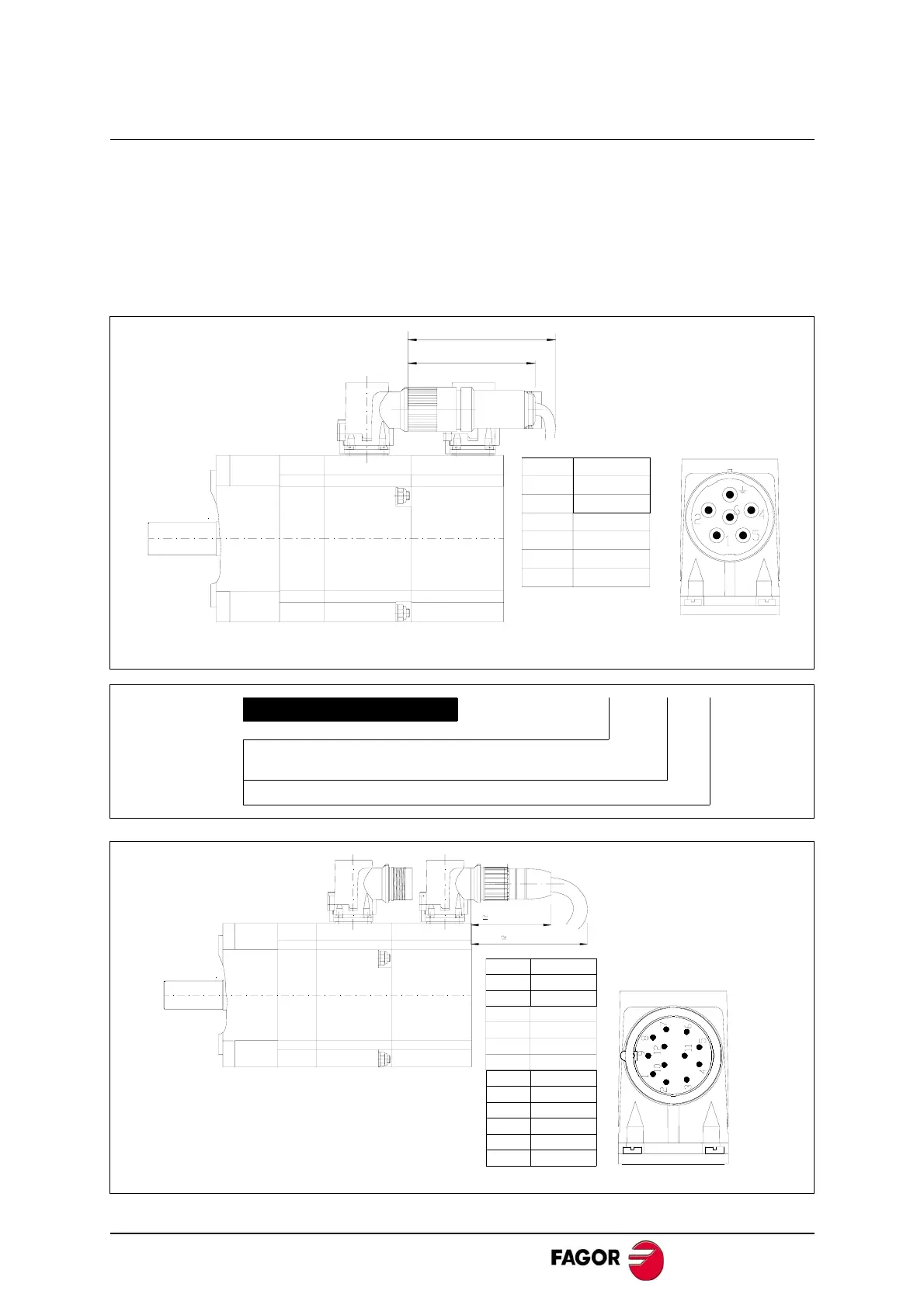
It includes the connectors of the brake itself (pins 4 and 5). A voltage between 22 V
DC and 26 V DC releases the shaft. When installing the motor, verify that the brake
releases the shaft completely before turning it for the first time.
Connecting the motor windings in the order indicated on the connector (U, V, W), the
shaft will turn clockwise (CWR, clockwise rotation).
Pins 3 and 4 of the encoder connector correspond to the thermistor PTC KTY- 84 for
monitoring motor temperature.
POWER CONNECTOR
Example: MC - 20/6
MOTOR CONNECTOR
MC-20/6
Straight
CURRENT
20 A
Note. Their connection base is viewed from the outside of the motor.
MOTOR POWER
CONNECTION BASE
97 [3.82]
80 [3.15]
2
1
PHASE U
PHASE V
PIN
SIGNAL
6
PHASE W
3
GROUND
4
BRAKE (+)
5
BRAKE (-)
CONNECTION BASE OF A
"SINCOS" ENCODER.
References A3 and E3.
91 [3.58]
62[2.44]
9
8
COS
CHASSIS
7 -485
10
GND
11
N.C.
12
+ 8 V DC
2
1
REFCOS
+485
PIN SIGNAL
3
KTY 84 (-)
4
KTY 84 (+)
5
SIN
6
REFSIN
Note. Their connection base is viewed from the outside of the motor.
 Loading...
