Digital Brushless AC servo drive system - Ref.0707 MCS- 35/92
About the connection
All the cables must be shielded, to reduce the interference on the control of the motor
due to the commutation of the PWM.
The shield of the motor power cable must be connected to the chassis screw at the bottom
of the module and it, in turn, taken to mains ground.
The command signal lines must be shielded twisted pairs.
The shield must be connected to the voltage reference at the module (pins 2, 4 or 10
of X1).
All the pins with the GND symbol ( 2, 4 and 10 ) are the same electrical point and are
interchangeable.
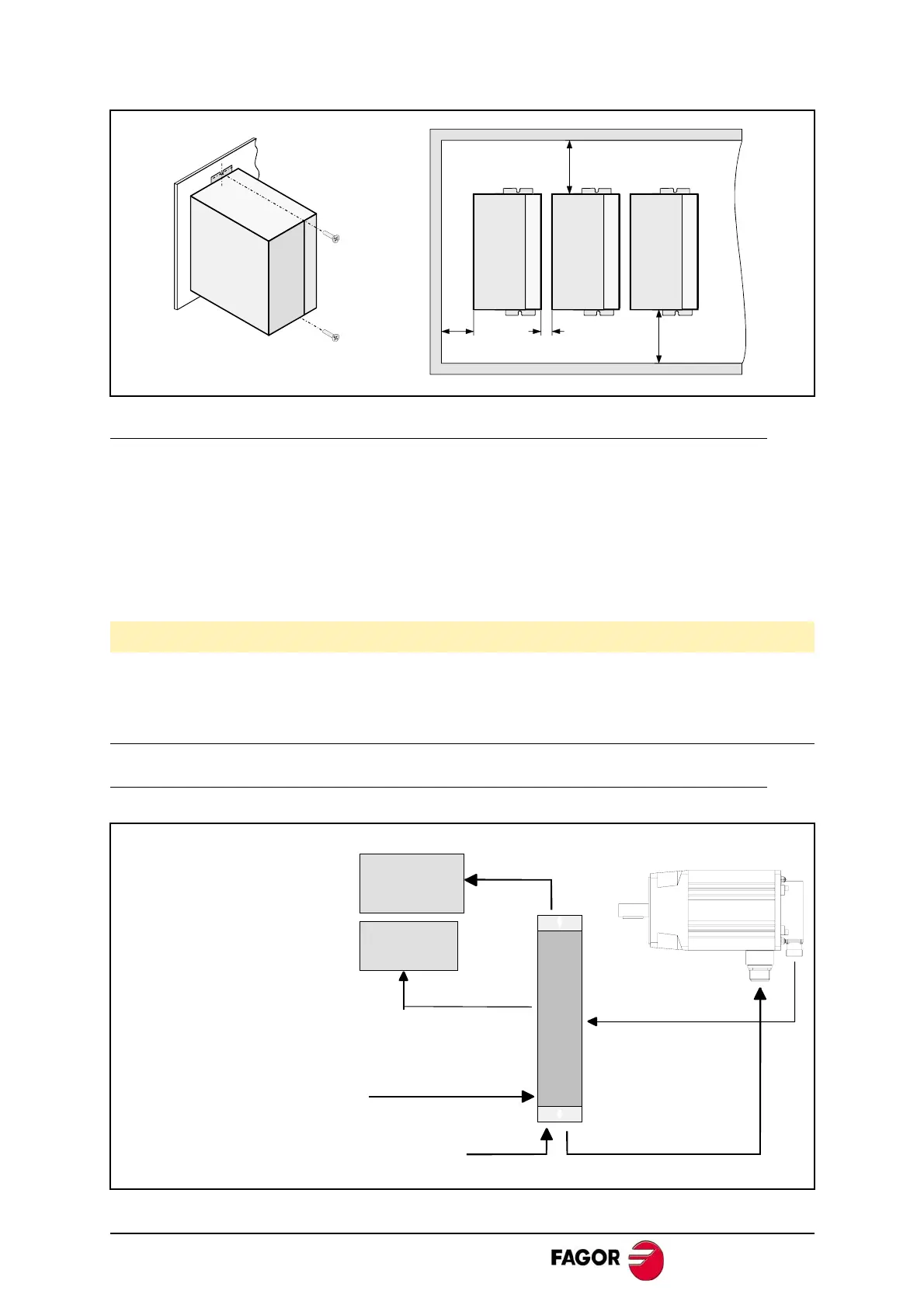
Electrical connections
Basic interconnection diagram
See section: Encoder feedback connection.
Keep the signal cables away from the power cables.
M6
M6
>50mm
>50mm>10mm>30mm
CNC
Mains
FXM or FKM
IECD Cable
MPC Cable
* SEC Cable
Ballast
(optional)
MCS DIGITAL
Mains
SEC-HD Cable
EEC Cable
EEC-SP Cable
(*) Note that the SEC
cable to connect it to the
8055 CNC and the SEC-HD
cable to connect it with the
8040 or 8055i CNC.
 Loading...
