Digital Brushless AC servo drive system - Ref.0707 MCS- 45/92
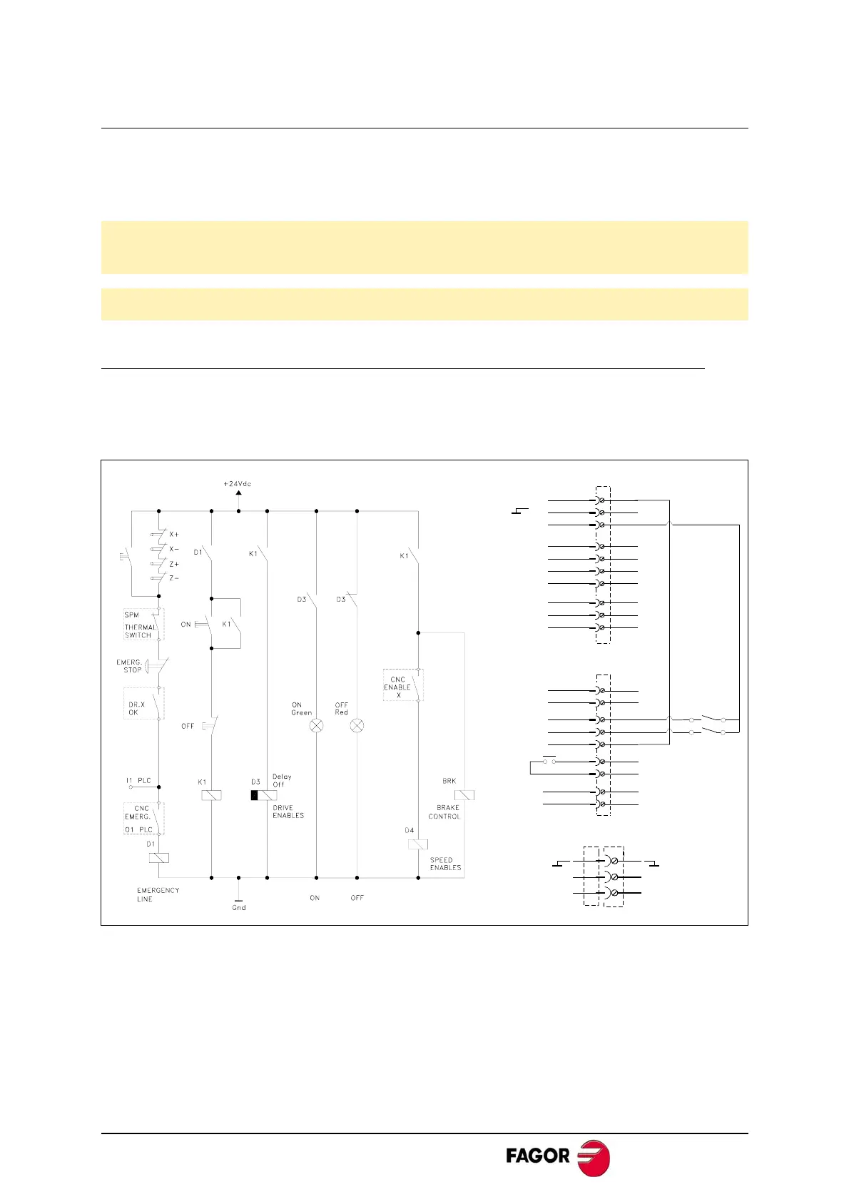
Diagram of the electrical cabinet
This is an orientative diagram for the installation of the electrical cabinet. This diagram
may be modified according to the requirements of each application.
It includes a simple circuit for the voltage supply of the brake of the servo motors.
Mains connection and maneuver diagram
The delayed disconnection of D3 contacts is useful so:
The Drive Enable stays active while the motor brakes at maximum torque.
The brake holds the motor after it has stopped..
Warning. When installing an auto-transformer, the secondary must have a star
connection and its middle point must be connected to GND.
Warning. The use of fuses is a must.
X1
9
8
10
-12 V
+12 V
2
1
3
5
4
6
7
7
6
DR.OK
4
3
5
SPEED
DRIVE
COMMON
DR. X
1
2
9
8
X2
L2
L1
X3
D3
D4
OK
L2
L1
 Loading...
