Digital Brushless AC servo drive system - Ref.0707 MCS- 13/92
Power connectors and encoder output
The power connector includes the brake terminals (E, F). A voltage between 22 and 26
V DC applied to the brake releases the shaft
. When installing the motor, verify that the
brake releases the shaft completely before turning it for the first time. Connecting the
motor windings in the order indicated on the connector (U, V, W), the shaft will turn
clockwise ( CWR, clockwise rotation ).
Pins I and J of the encoder connector correspond to the thermistor for monitoring motor
temperature.
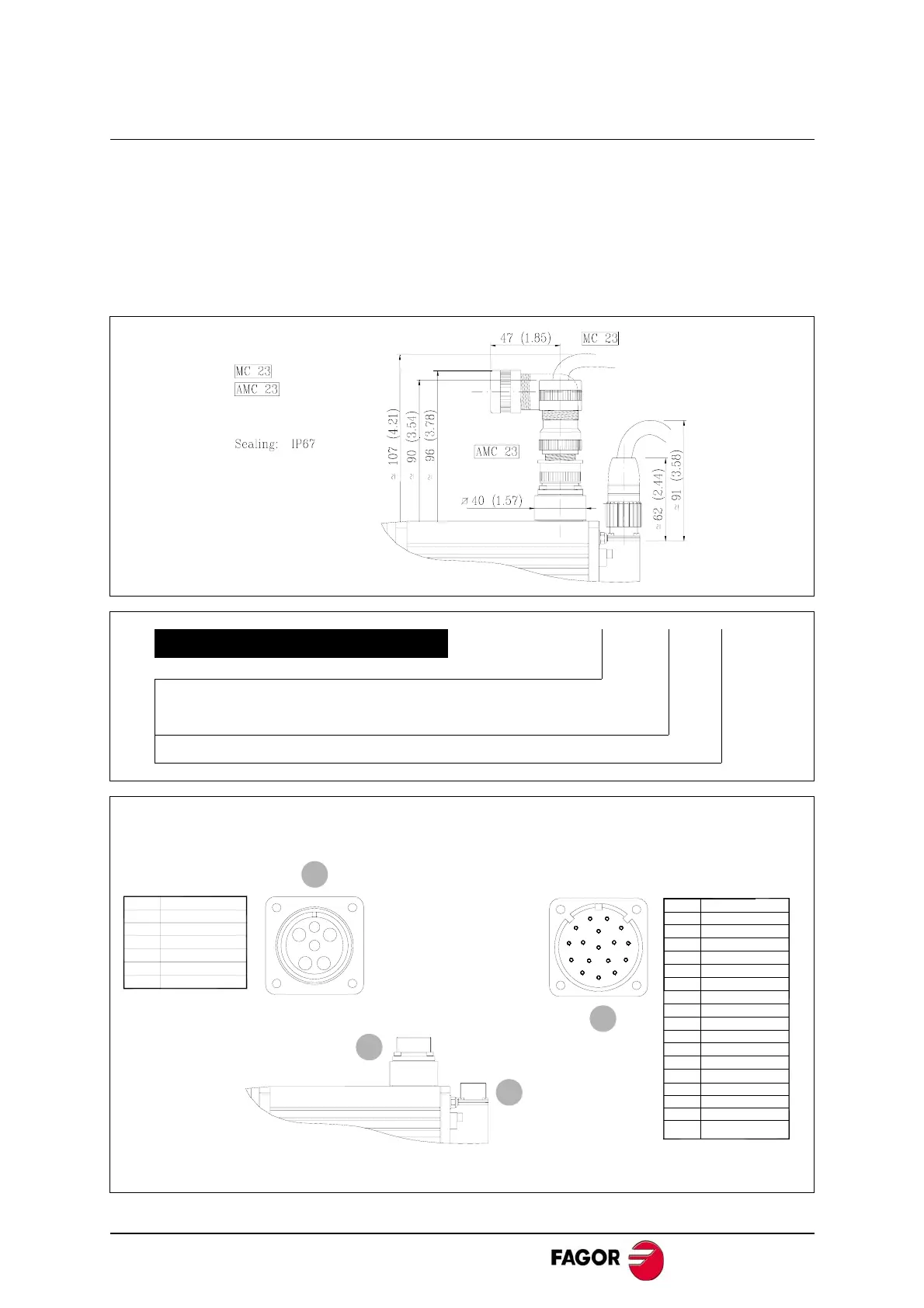
POWER CONNECTORS
Example: MC - 23
MOTOR CONNECTOR
MC Straight
AMC Angled
CURRENT
23 Amperes
CONNECTION BASE OF AN
"INCREMENTAL TTL" ENCODER
Reference mark (I0)
MOTOR POWER
CONNECTION BASE
MC 23 or AMC 23
A
BC
D
E
F
PIN
SIGNAL
APhase U
B
Phase V
C
Phase W
D
Ground
E
Brake (+)
F
Brake (-)
IOC-17
PIN
SIGNAL
AA
B
*A
C
+ 5 V DC
D
Ground
E
B
F*B
G
Z
H*Z
I Thermistor
J Thermistor
KU
L*U
MV
N*V
O
W
P*W
Q Shield + chassis
A
B
C
D
E
F
G
H
I
J
K
L
M
N
O
P
Q
2
1
1
2
Note. their connection bases are viewed from the outside of the motor.
 Loading...
