INSTALLATION ST100 Series Flow Meter
12 Fluid Components International LLC
Flow Element Wiring
The ST/STP102A can be configured with one integral and one remote flow element or with two separate flow elements and remote electron-
ics. Wiring diagrams for these configurations are located in Appendix B. Each of the flow elements on the ST102A/STP102A are connected to
the transmitter using an 8-conductor shielded cable as specified in the Instrument Wiring Table 1.
ST/STP102A Electronics Description
The electronic transmitter for the ST/STP102A type instruments provides a two point averaged flow and temperature output on the display
and the customer selected output mode, analog or digital.
Analog 4-20mA output: factory default setup
• Output #1 – Two point average Flow
• Output #2 – Two point average Temperature
• Output #3 – Pressure, available on STP models
HART output
• Command 9 – Slot 0, 2, 4: Two point average Flow.
• Command 9 – Slot 5: Two point average Temperature
• Command 9 – Slot 6: Pressure
Fieldbus output
• Flow AI Block – Two point average Flow
• Temperature AI Block – Two point average Process Temperature
• Process Transducer block – index 13, PRIMARY_VALUE (Average FLOW)
• Process Transducer block – index 15, SECONDARY_VALUE (Average TEMPERATURE)
Modbus output
• Command 3 – Two point average Flow
Two point average Temperature
Pressure, available on STP models
Totalizer
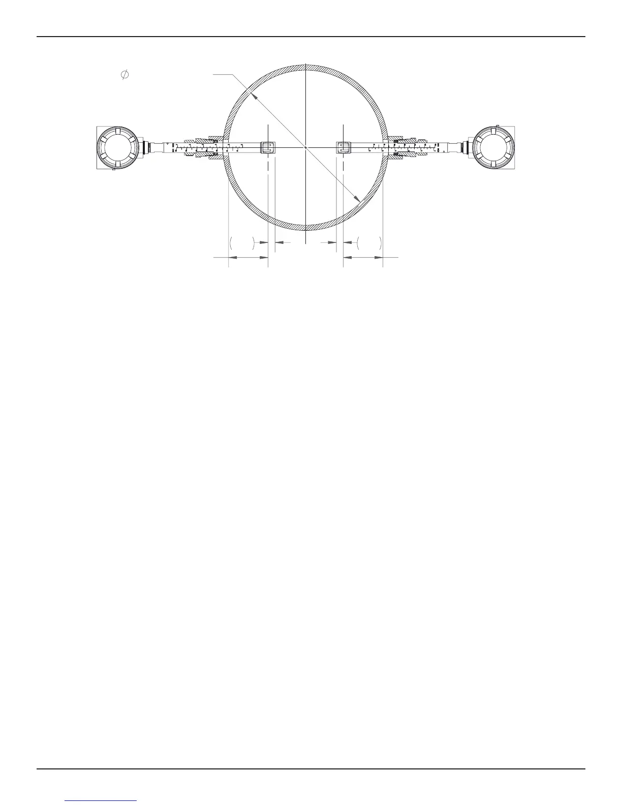
Pipe I.D > 12.0"
14.6% Pipe I.D
.50
14.6% Pipe I.D
.50
C
L
C
L
Figure 5

 Loading...


