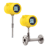
INSTALLATION ST100 Series Flow Meter
10 Fluid Components International LLC
Adjustable/Retraceable Packing Gland Mounting
For applications involving the use of packing glands refer to drawings located in Appendix A for additional detail.
NPT and flange mounted gland are available. Isolation valves are typically used in packing gland applications.
• Follow the pipe thread or flange mount procedures as described in previous sections.
• Tighten the packing nut until the internal packing is tight enough to prevent excess process leakage but also allow the insertion pipe to be
inserted into place. Orient the flat and flow arrow properly.
• Proceed to insert the flow element into process media pipe. For the medium pressure packing gland, use the adjusting nuts on the all-thread to
pull the flow element into proper position. Tighten the opposing lock nuts.
• Tighten the packing nut another ½ to 1 turn until tight (approximately 65 – 85 ft-lbs)
• On low pressure packing glands, align the split ring collar with connecting strap on packing nut. Tighten the two ¼-28 cap screws on the split
ring locking collar.
STP100 and STP102A Flow Element Installation
The Model STP100 and STP102A add an additional pressure transducer measurement as a third process variable output. The process connections
available on the STP model include the standard connections available on the ST model except the compression fitting. The ST102 has two probe
assemblies. Available process connections include:
• Retractable Packing Gland
• Fixed NPT
• Flanged
All flow element mounting and securing instructions for the selected process connections are identical to the ST100. These details are provided in
the previous process connection mounting sections.
The pressure limitation for the STP model will be determined by the selection of the pressure transducer. The available options include 50, 160, 500
and 1000 psig (3.44, 11.03, 34.47 and 69.95 bar) maximum pressure ranges.
The pressure transducer is offered in two different temperature service ranges:
• Standard: 32 to 176°F (0 to 80°C)
• Explosion Proof (Ex): -22 to 212°F (-300 to 100°C)
The pressure transducer is located inside the rectangular shaped enclosure attached to the flow element. The pressure tap is located in the center of
the two thermowells and extends through the center of the insertion pipe into the enclosure where the transducer is located. Because the pressure
transducer is located several feet away from the process media, at the end of a dead head tube assembly, the pressure transducer will be exposed to
the external ambient temperature of the flow element.
Flow Element Wiring
The STP100/102A can be configured with integral or remote electronics. Wiring diagrams for these configurations are located in Appendix B.
Remote configurations require a 10-conductor shielded cable as specified in the Instrument Wiring Table 1.
STP100/102A Electronics Description
The electronic transmitter for the instrument provides flow, temperature and pressure output on the display and the customer selected output
mode, analog or digital.
Analog 4-20mA output: factory default setup
• Output #1 – Flow or Two point average Flow
• Output #2 – temperature or Two point average Temperature
• Output #3 – Pressure

 Loading...