ST100 Series Flow Meter TROUBLESHOOTING
Fluid Components International LLC 39
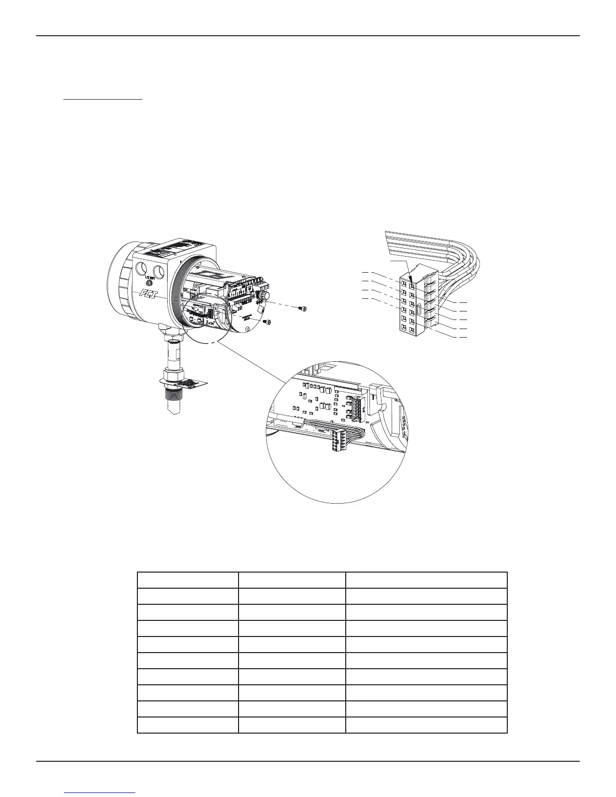
Troubleshooting the Flow Element
This procedure is different depending on the instruments configuration, Integral or Remote.
Integral Configuration (Reference Figure 18 shown below.)
1. Turn off the input power to the instrument.
2. Remove the two M4 socket head screws securing the electronics into the enclosure. A third M4 socket head screw is used to ground the
electronics assembly, this screw can remain in place and will prevent the electronics from falling out of the enclosure.
3. Slide the electronics assembly out of the enclosure until the Flow Element connector TB1 is accessible.
4. Note the location of the positive locking tab on the connector. Carefully remove the plug from the connector.
5. Orient the pin 1 as shown in the figure below. Using an ohmmeter with pin type probes, measure and record the ohm values between the
pins identified in the Integral Flow Element Resistance Table.
C01234-1-1
#2 HTR EXC
#1 HTR EXC
PIN 1
3 HTR RTN
4 ACT EXC
5 ACT SEN
7 GND
9 REF SEN
6 GND SEN
8 REF EXC
Probe A Probe B Approximate Resistance
1 HTR EXC 3 HTR RTN 110-118 ohms
4 ACT EXC 5 ACT SEN 0 ohms
8 REF EXC 9 REF SEN 0 ohms
9 REF SEN 5 ACT SEN 2160 ohms
6 GND SEN 4 ACT EXC 1080 ohms
6 GND SEN 5 ACT SEN 1080 ohms
6 GND SEN 8 REF EXC 1080 ohms
6 GND SEN 9 REF SEN 1080 ohms
6 GND SEN 7 GND 0 ohms
Integral Flow Element Resistance Table
Figure 18

 Loading...


