ST100 Series Flow Meter APPENDIX C - ADDITIONAL INFORMATION
Fluid Components International LLC 83
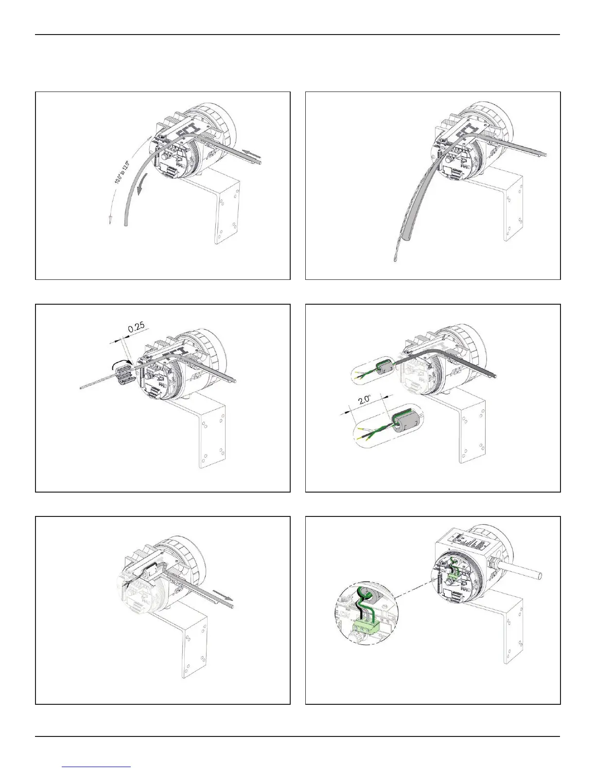
STEP 1
STEP 3
STEP 5
STEP 2
STEP 4
STEP 6
Insert DC power supply cable through enclosure conduit port as shown.
Measure 10 to 12 inches beyond interface board.
Slice open the jacket 10 to 12 inches and cut.
Cut wires 2 inches from edge of ferrite and strip ends as shown.
Insert and secure DC power supply wire leads to terminal connector as shown.
Slide ferrite over power supply cover while pulling on the power supply cable.
Position ferrite face to coincide with edge of housing.
a. Loop wires around ferrite body.
b. Keep .25 inches from ferrite to edge of cable jacket as shown.
c. Close ferrite.
Instructions: Installing Ferrite Onto ST100 Series DC Power Cable

 Loading...


