Page 33 of 91
PART 7
POINT PROGRAMMING
7.1 POINT INSERTION
The acquisition of a point from the control panel, can be executed with four different procedures of acquisition
addressing:
1. Acquisition for installation (valid only detectors);
2. Acquisition for activation;
3. Acquisition for serial number (only if the serial number label is present in the point);
4. Acquisition for preset address.
For a suitable selection of the acquisition procedure, refer to the “PRELIMINARY REMARKS FOR A CORRECT
INSTALLATION”.
Remember that:
The acquisition of points through the installation is preferred when it is necessary to insert further un-addressed
detectors on the loop, but on already installed base, along and already active loop and that presents already
addressed points (example: isolators modules – buttons).
The acquisition of points through starting provides for the activation of already installed points along the loop. Such
points must have address 0.
The acquisition of points through serial number provides for the acquisition of a point through the research of the
series number of the same point.
The acquisition of points through the preset address provides for the acquisition of further already installed points on
the loop and addressed previously. The user must not have points with address 0 on the loop.
HOW TO ASSIGN THE DETECTORS WITH ADDRESS 0
• Supply the detector placed on the base with power at 24 Vdc (it is possible to use the auxiliary output of
the same control panel, connecting the +24 to the clip 6(+) of the base and the –24 to the clip 5(-) of the
base).
• Approach to the detector with a magnet and a wait the leds view a long flash.
7.1.1 Procedure for the acquisition of a point
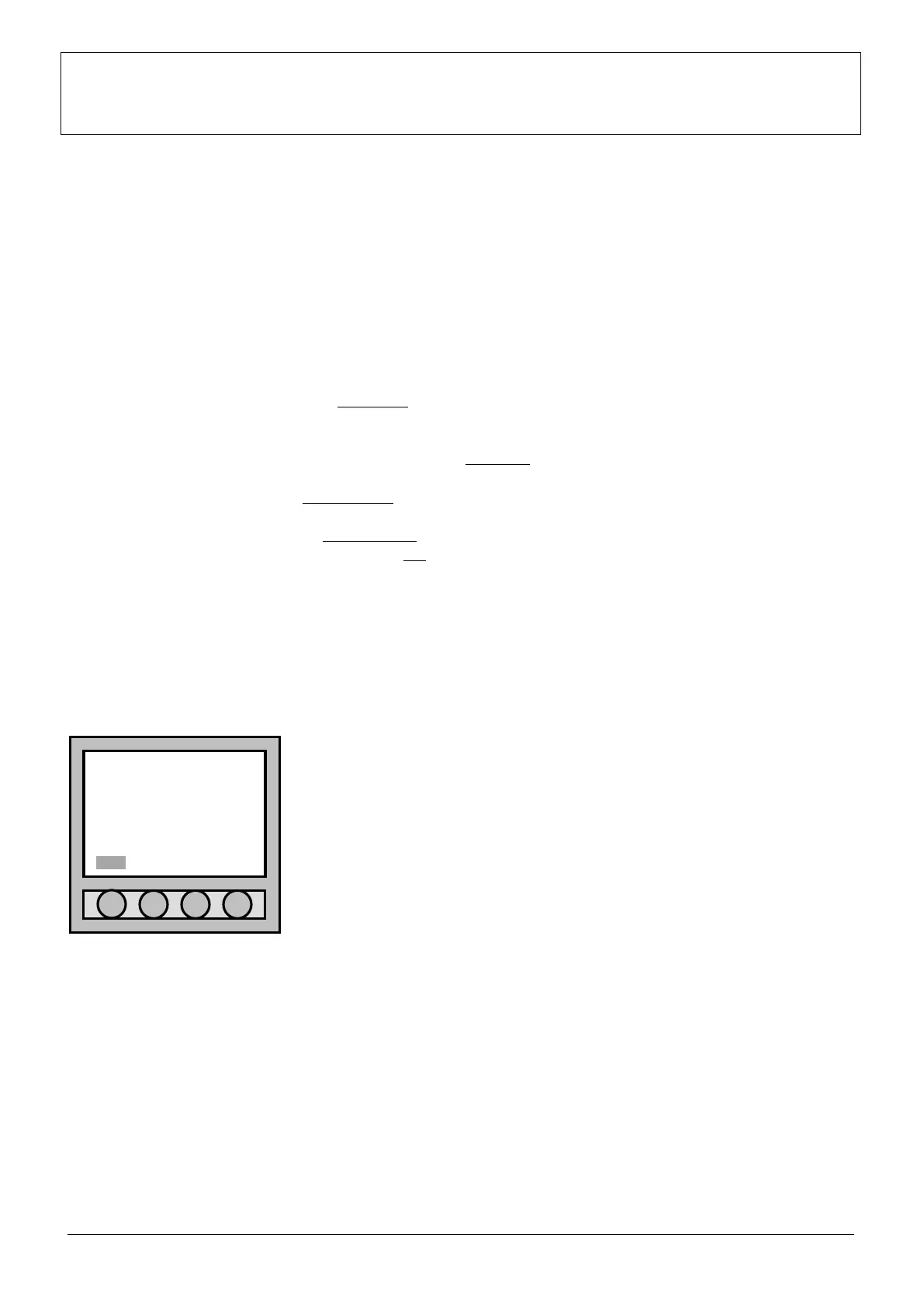
In normal functioning, the date, the hour and the message “
SUPERVISOR MODE” is viewed on the display. The message “Menu”
appears low on the left. Typing “Menu” the display lightens and passes to
the “Main menu” where parameters of the control panel can be modified or
added with suitable passwords.
05/02/2007 18:30:58
NO SUPERVISOR MODE
ANALOGUE FIRE
CONTROL PANEL
Menu