Page 48 of 91
Output setting
•OUTPUT ADDRESS: 002
TYPE: SIREN
DEVICE: SUPERV.RELAY
OUT OF SERVICE: NO
FAULT: NO
STATUS: DISABLED
TEST RUN: NO
ACTIV. DELAY s: -
MAN.ALARM ACTIV: NO
OUT ACTI.TIME s: -
INVERT: NO
Esc. Pre. Next Mod.
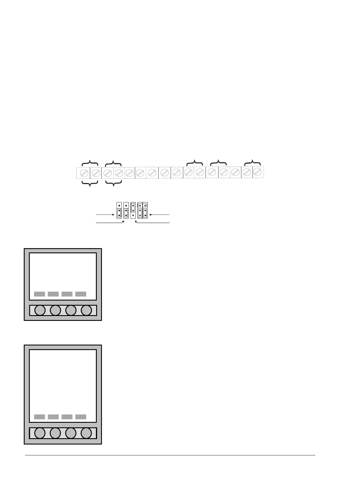
Output setting
•OUTPUT ADDRESS: 001
TYPE: 24 Vdc
DEVICE: PWR SUPPLY.
OUT OF SERVICE: NO
FAULT: NO
Esc. Pre. Next Mod.
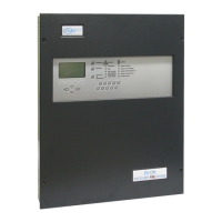
9.2 CONTROL PANEL OUTPUT
9.2.1 Output description
Selecting “CONTROL PANEL OUTPUT” the outputs inside the control panel will be able to be programmed as
follows:
Ø (out5) Clips RL1 (SEL4): relay 1 is a clean relay no supervised that can be programmed NO/NC;
Ø (out4) Clips RL2 (SEL3): relay 1 is a clean relay no supervised that can be programmed NO/NC;
Ø (out9) Clips OC4: open collector No 4 programmable for typology of alarm and zone;
Ø (out8) Clips OC3: open collector No 3 programmable for typology of alarm and zone;
Ø (out7) Clips OC2: open collector No 2 programmable for typology of alarm and zone;
Ø (out6) Clips OC1: open collector No 1 programmable for typology of alarm and zone;
Ø (out3) Clips FAULT (SEL1,2): supervised output of fault;
Ø (out2) Clips –S +S: supervised siren;
Ø (out1) Clips +24 –24: auxiliary power supply 24Vdc.
FAULT
S
H
I
OC
1
RL2
RL1
SEL4
SEL3
SEL1
SEL2
9.2.2 24Vdc output
It is a power supply output of 24Vdc.
For the information about the menu items, to see the chapter 9.1.4.
9.2.3 Siren output
It is a output of supervisory type siren.
For the information about the menu items, to see the chapter 9.1.4.