Page 73 of 91
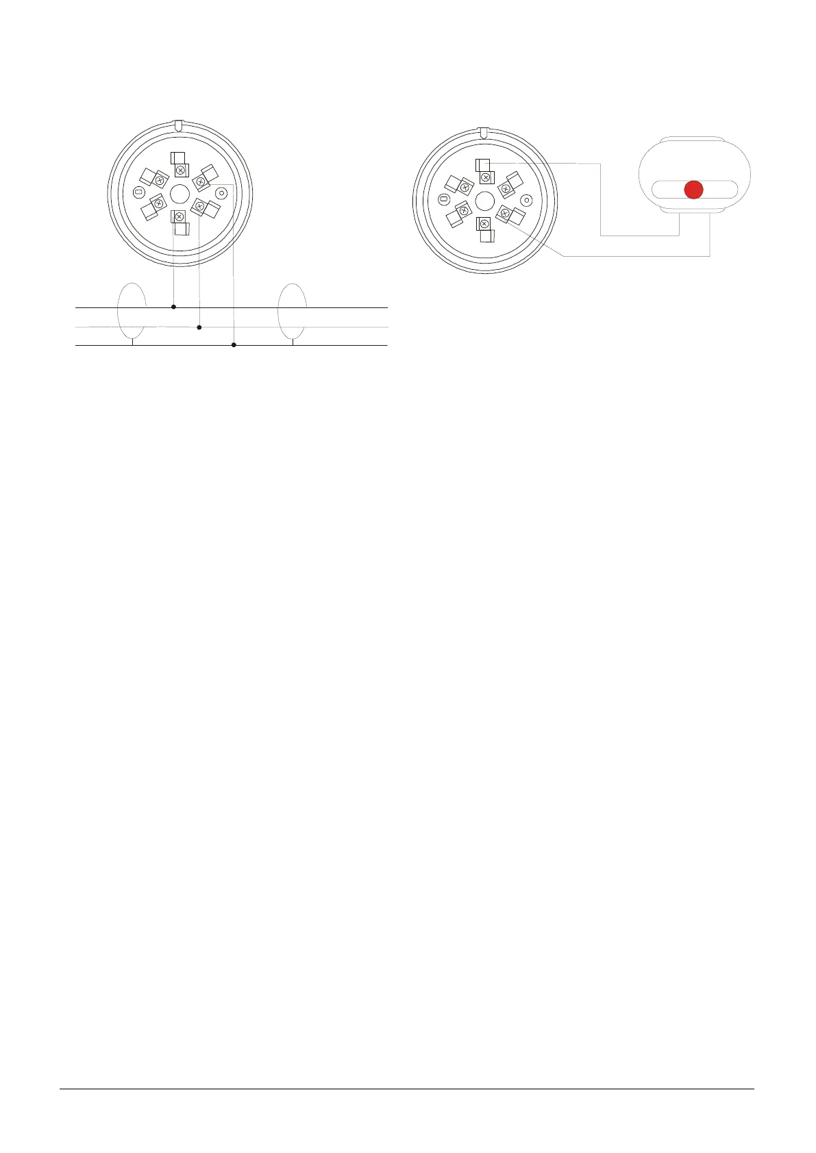
15.1.6 Electrical schemes
2
3
1
6
5
4
SH I
Lo op +
Lo op -
SH I
Lo op +
Lo op -
CONNECTION TO LOOP:
15.2RESETTABLE BUTTON
Manual reset alarm button for control panel.
15.2.1 Input and output description
INPUT: The input is of the type of balanced resistance of the 27K• value. The input signal is given opening the
circuit between the two clips and the resistance; but, if it is short circuited, a fault in the input line is indicated. The
maximum length of the input line is 8m.
OUTPUT: the output is a Open Collector type. It is necessary to use a CMOS interface with a low current supply
to control a relay.
The input and output can be programmed with different types of meaning (Example: Alarm fire, technological...).
15.2.2 Button addressing
For the addressing in loop it is necessary to use a magnet near the reed. For the procedures, refer to the manual
of the control panel.
15.2.3 Manual zero setting of the address
Normally the factory address is equal to 0 (zero). If you must assign the address to zero, give manually 24V to the
detector and, after ten seconds, approach reed a magnet and wait for the led to make a long flash signal.
15.2.4 Point setting
In the “Point setting” menu (submenu of “POINT” item) there are different parameters for this detector. For
the output setting, see chapter PART 9).