26
© Ferno s.r.l. Rel.05042024
XT Series Extrication Devices
4.3 - XT PRO assembly
4.3.1 QHI (Quick Head Immobilizer)
assembly
The Quick Head Immobilizer must be applied before using
the XT device.
1.Before its application, make sure that the extrication
device is placed on a at surface and the part where the QHI
head immobilizer will be applied is clean and dry.
2. Peel off the sticker lm placed under the QHI, ensuring
that the black part stays on the QHI.
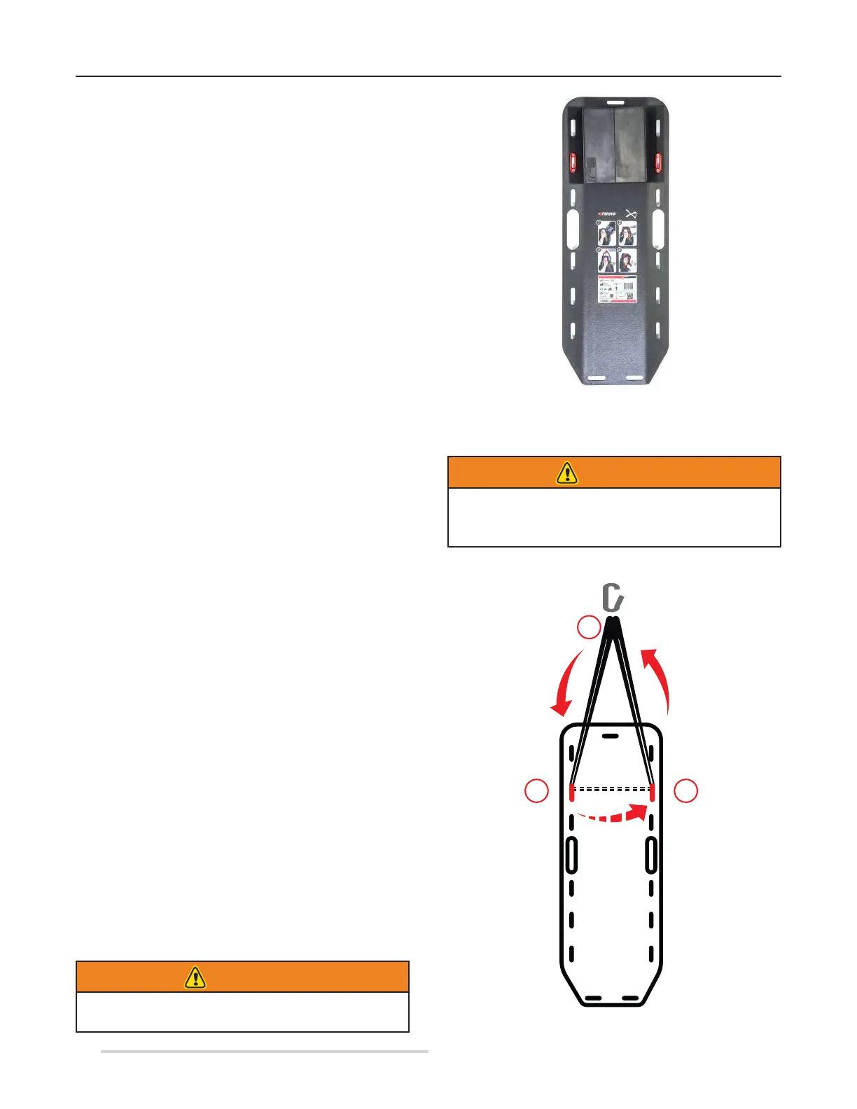
3. Centre the QHI on the upper part of the extrication device,
close to the head end hole no. 1.
4. Press the QHI so that its sticker perfectly adheres to the
surface (Figure 25).
The installation procedure for the QHI is identical for all
versions of the XT. For more information, see the QHI
(Quick Head Immobilizer) assembly paragraph of the XT
PLUS section.
Figure 25 - QHI positioning on XT board
WARNING
In case of purchase of a PRO KIT, please assemble the
red reinforcing slots before applying the restraints.
Please refer to chapter Spare parts assembly.
In case of extrications or transports in complex environments,
the XT can be hanged by means of an anchor device (EN
566:2006), such as a validated textile ring with a minimum
length of 120cm, and a connector (EN 362).
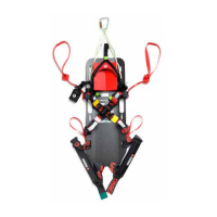
In order to apply the strap proceed as follows:
1. Turn XT PRO so that you can see the back of the board.
2. Insert the two ends of the strap into the holes reinforced
by the red slots (holes no. 3 and no. 14), so that they protrude
from the front of the board (Figure 27).
3. Connect the two ends of the strap with the supplied snap
hook (Figure 27C).
WARNING
For the specic maintenance of strap and hook,
refer to the manufacturers of the devices.
4.3.2 Assembling the hanging strap
and the snap hook
A
B
C
Figure 26 - Lifting tape insertion