13
© Ferno s.r.l. Rel.05042024
XT Series Extrication Devices
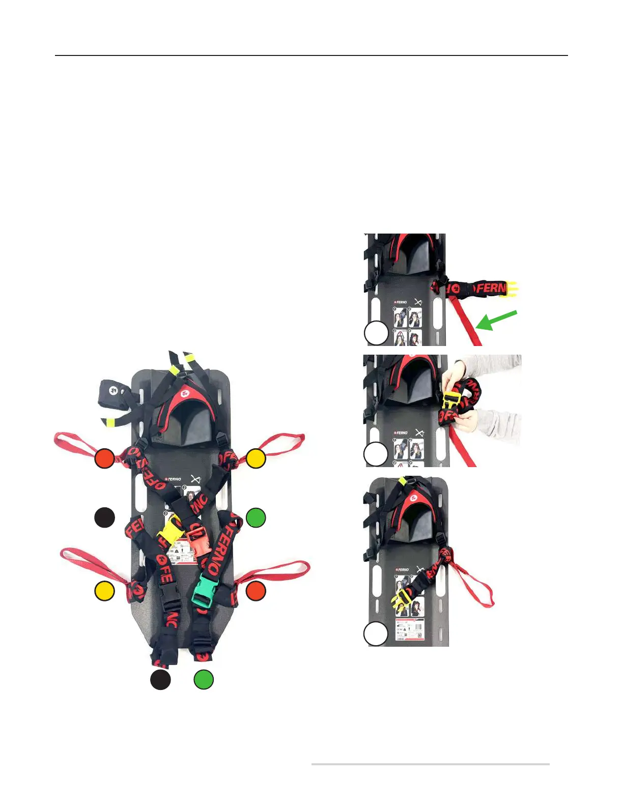
3.3.4 Assembling the restraints
The XT Plus extrication device is equipped with two upper
chest restraints (yellow and red) and two lower groin
restraints (black and green).
Upper chest restraints should be applied in such a way that
they are in a crossed conguration when applied to the
patient.
Groin restraints, on the other hand, should be applied in
such a way that they fasten on the same side.
Each restraint consists of two pieces. Position the restraints
so that the buckles follow the arrangement shown in Figure
4.
The chest restraints are equipped with integrated red lifting
and carrying handles, to which the two extension rings can
be added if necessary.
The restraints must be applied before using the XT device.
For their application and the identication of the right hole
on the device, refer to Figure 4.
Figure 4 - Conguration of restraints
13
12
10
8
9
7
5
4
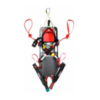
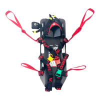
YELLOW CHEST RESTRAINT
In order to apply the yellow chest restraint:
1. Insert the slot of the restraint with the male end into hole
no. 4 on the extrication device, with the stitching facing the
operator, making sure that the red handle remains outside
the board (Figure 5A).
2. Insert the yellow buckle into the newly positioned
restraint slot (Figure 5B).
3. Pull the restraint to tighten the loop knot, ensuring that the
red handle always remains on the outside, at the rear of the
board (Figure 5C).
5A
5B
5D
Figure 5 - Yellow restraint application
(end with male buckle)