42
© Ferno s.r.l. Rel.05042024
XT Series Extrication Devices
WARNING
Check that all the slots of the XT Military allow the
tape and restraints to pass.
5.2.1 General technical specications
Ferno reserves the right to change the specications without
notice. For further details, please contact Ferno's Customer
Service (page 2).
COMPONENTS OF THE XT PRO EXTRICATION DEVICE
● Board with holes for restraint fastening
● QHI (Quick Head Immobilizer)
● Neoprene triangular head immobiliser
● Chin strap for QHI
● Yellow and red chest restraints with colour-coded
stitching and integrated red lifting and carrying handles
● Black and green groin restraints with colour-coded
stitching and integrated red lifting and carrying handles
● Thigh padding for groin restraints (x 2)
● Auxiliary handles (x 2)
● Snap hook
● Lifting tape
● Longitudinal cushion to support the cervical spine,
in case of positioning the device on a patient wearing
bulletproof vest and helmet.
Materials
XT Board Composite material
Quick Head Immobiliser Polyurethane
Restraints Nylon
Buckles Aluminium alloy
Triangular head immobiliser and chin strap Neoprene
Assembled product specications
Length 830 mm
Width 300 mm
Thickness 60 mm
Weight (including accessories) 3.4 kg
Load capacity 160 kg
WARNING
Untrained users may injure themselves, cause
damage and/or physical harm. Allow only trained
and qualied sta to use the XT extrication device.
WARNING
Never exceed the load capacity of the extrication
device specied in this manual.
5.3 XT MILITARY assembly
For the assembly procedure of the XT MILITARY, please
refer to what is explained in the XT PRO assembly section,
as the two only differ in colour.
5.4 Extrication procedure
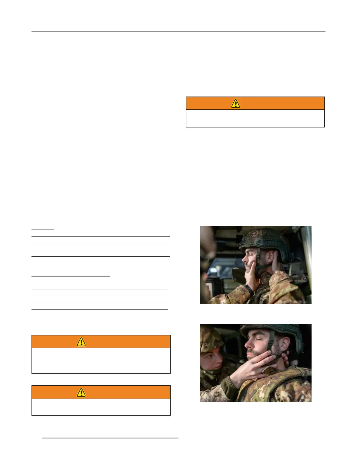
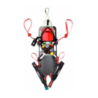
Once access to the passenger compartment has been
gained, manually stabilise the casualty's cervical spine. This
procedure can be performed by the operator approaching
from the side of the passenger compartment (Figure 51), or
by another operator entering from the opposite side (Figure
52) or from the back of the passenger compartment, if
accessible.
Figure 51 - Approaching the passenger compartment
from the casualty's side
Figure 52 - Approaching the casualty from the opposite
side