60
© Ferno s.r.l. Rel.05042024
XT Series Extrication Devices
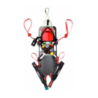
Possible variant on restraint application
You can attach the restraints as shown in Figure 106, so that the male buckles are both on the same side.
Alternatively, if you want to reproduce the “ready-to-use” conguration as in the XT Plus and Pro, you can choose to t
one of the two restraints (yellow or red) with the buckles inverted as shown in the drawing, so that, by attaching them
together on the sides, the board remains free.
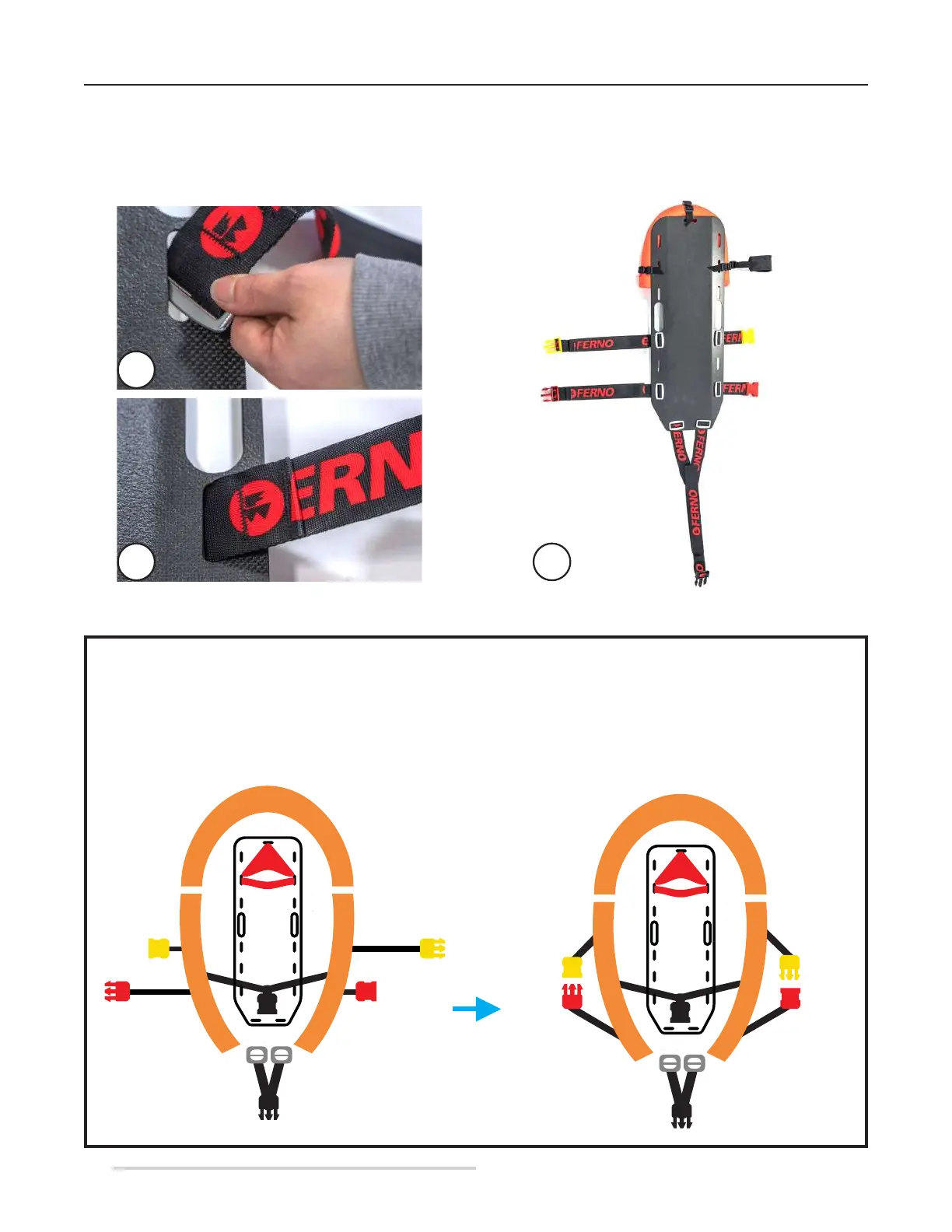
In order to install the restraints on the XT Floating, the metal buckle of each restraint must be inserted into the respective slot
so that it remains on the back of the board and positioned so that when pulled, the restraint remains xed on the XT Floating
(Figure 107A, 107B, 107C). Perform this operation for all restraints, following the arrangement shown in Figure 106.
Figure 107 - Application of XT Floating restraints
107B
107A
107C