100
EN
Cod. 3541V991 - Rev. 06 - 10/2022
OMNIA ST 3.2
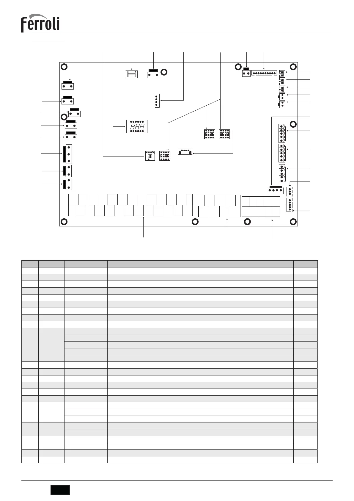
7.6.5 Hydronic board
&1
&1
&1
6
',6
&1
&1
&1
&1
&1
&1
&1
&1
&1
&1
6
&1
&1
6
6
&1
&1
&1
&1
&1
&1
&1
&1
&1
&1
1
A
2
B
3
X
4
Y
5
E
6
P
7
Q
8
E
9
H1
10
H2
1
SL1
2
SL2
3
H
4
C
5
6
1ON
7
1OFF
8
910
11
12
3242
N
21
N
20
IBH1
19
18
13 14
L1
15
16
17
N
22
2ON
2OFF
P_cP_o P_sP_d
TBH
N
N
3ON
3OFF
NN
CN11
25
HT
29
30
31
DFT2
32
DFT1
26
R2
27
AHS1
28
AHS2
N
R1
CN7
CN30
fig. 22 - Hydronic board
Order Port Code Assembly unit Note
1 CN21 POWER Power supply to hydronic board B
2 S3 / Rotary dip switch /
3 DIS1 / Digital display /
4 CN5 GND Ground to hydronic board B
5 CN28 PUMP Power supply to internal water pump Pi B
6 CN25 DEBUG Port for IC programming /
7 S1, S2, S4 / Dip switch /
8 CN4 USB Port for USB programming /
9 CN8 FS Connection to internal water flow switch /
10 CN6
T2 * Port for temperature probe of refrigerant liquid side temperature of indoor unit (heating mode) B
T2B * Port for temperature probe of refrigerant gas side temperature of indoor unit (heating mode) B
TW_in * Port for temperature probe of inlet water temperature of plate heat exchanger B
TW_out * Port for temperature probe of outlet water temperature of plate heat exchanger B
T1 * Port for temperature probe of final outlet water temperature of indoor unit B
11 CN24 Tbt1 Port for temp. sensor probe in the plant tank A
12 CN16 Tbt2 Reserved /
13 CN13 T5 Port for temp. sensor probe in the DHW boiler B
14 CN15 Tw2 Port for outlet water for zone 2 temp. probe probe A
15 CN18 Tsolar ** Port for solar panel temp. sensor A
16 CN17 PUMP_BP PWM signal to internal water pump Pi B
17 CN31
HT Control port for room thermostat (heating mode) 1
COM Power port for room thermostat 1
CL Control port for room thermostat (cooling mode) 1
18 CN35
SG Port for smart grid (grid signal) 1
EVU Port for smart grid (photovoltaic signal) 1
19 CN36
M1 M2 Reserved /
T1 T2 Reserved /
20 CN19 P Q Reserved /
21 CN14 A B X Y E Port for communication with the display panel B
 Loading...