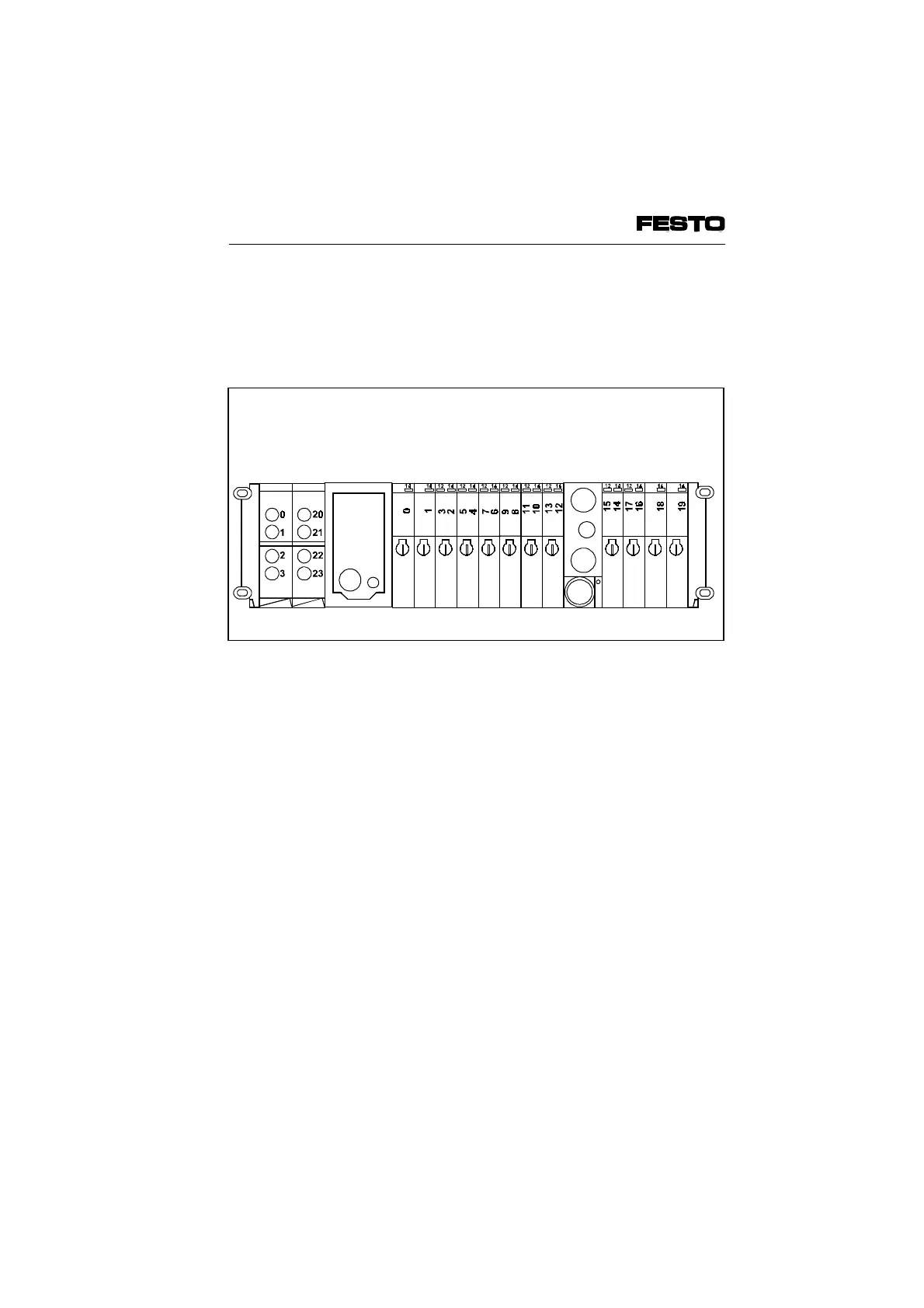
The diagram below shows an extension to the
standard fitting of the previous diagram and
shows the modifications which must be made to
the address assignment.
Remarks on Fig. 4/5
Air supply modules and intermediate air supply
modules do not occupy any addresses.
Input module
4-inputs
Output module
4-outputs
S sub-base
D sub-base
D sub-base
D sub-base
S sub-base
SUPPLY
Fig. 4/5: Address assignment of a valve terminal after extension/
conversion
VIFB6 - 03/05 4. Commissioning
9809c 4-15