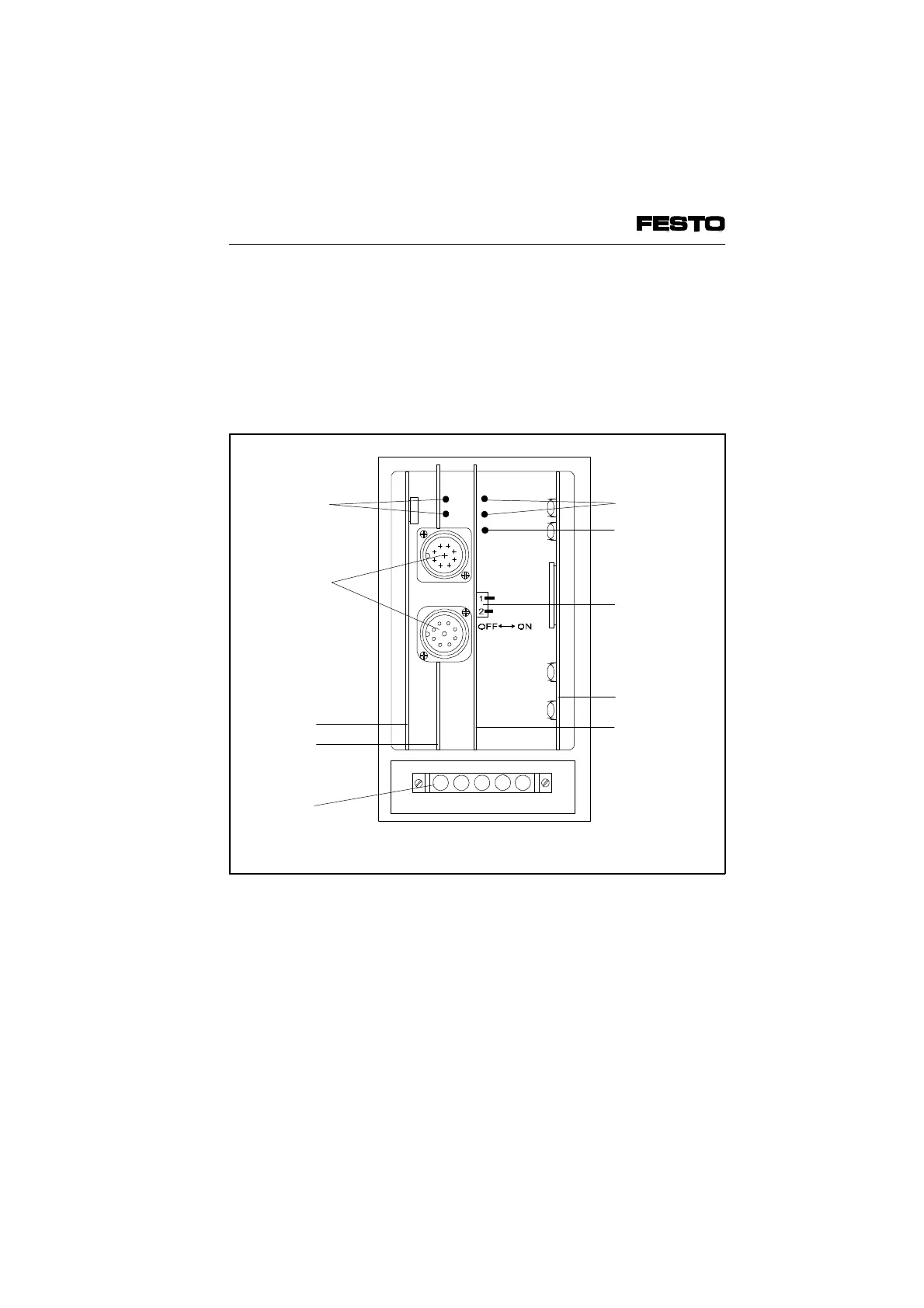
Configuration settings in the node
There are four PC boards in the node. Board 2
contains two LEDs and two connections for the
INTERBUS; board 3 contains three LEDs and a
switch for setting the valve test function and the
error reaction.
Green LED
Green LED
INTERBUS
interface
Board 1
DIL switch
Board 4
Board 2
Flat plug for
operating voltage
Red LED
Fig 3/6: Connection, display and operating elements of the node
VIFB6 - 03/05 3. Installation
3-18
9809c