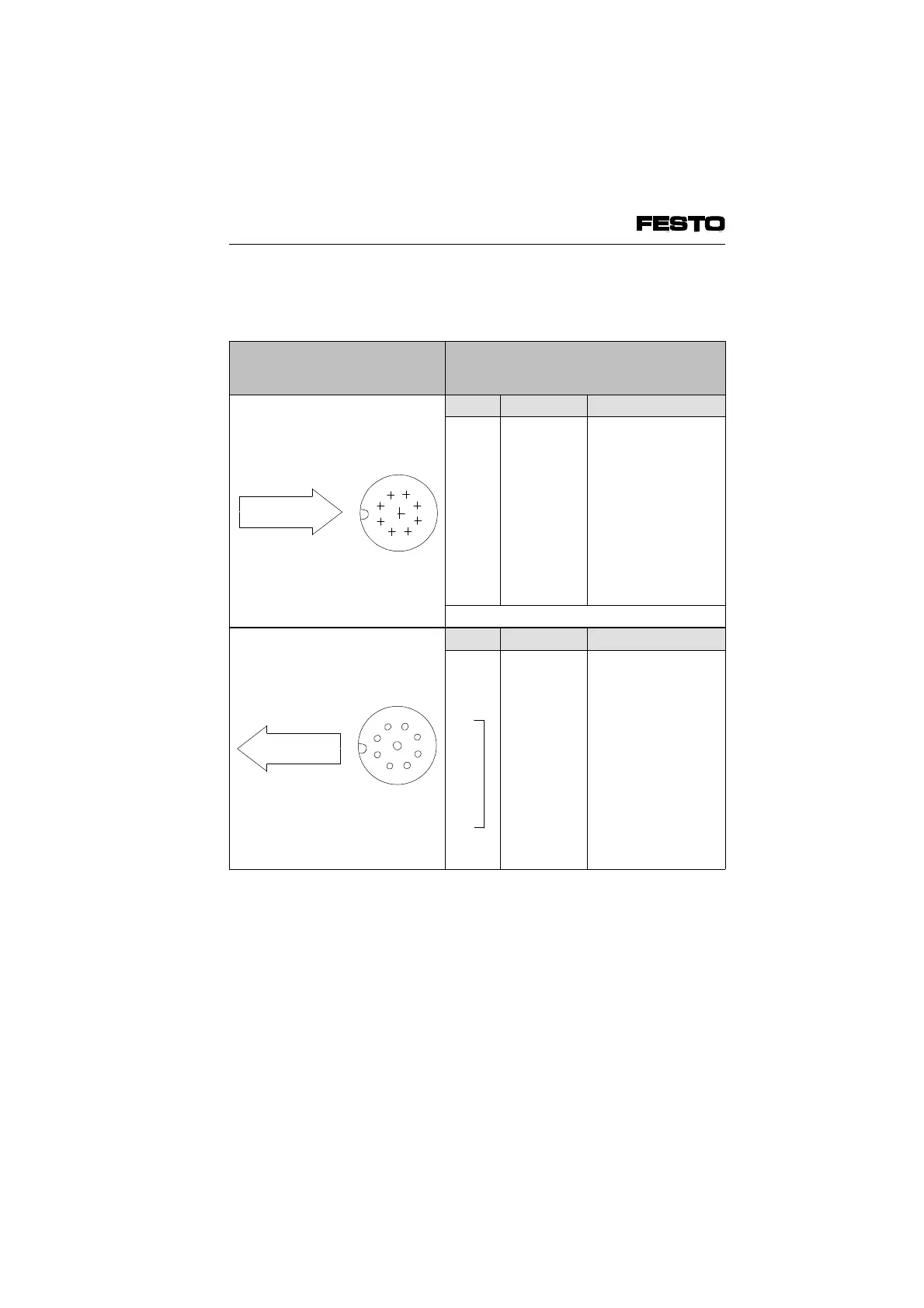
Connecting the installation remote bus for
non-floating operation
Plugs/sockets to be connected
(view of INTERBUS interface of
node)
Pin-Belegung*)
Top view
Pin-no. Designation Meaning
1
2
3
4
5
6
7
8
Sleeve
DO
/DO
DI
/DI
Earth
FE
+ 24 V
+ 0 V
Screen
Data out
Data out invers
Data in
Data in invers
Ref. conductor
Functional earthing of
inst. remote bus
inst. remote bus
supply
inst. remote bus
supply
Screening
*) Pins not listed must not be connected
Top view
Pin-no. Designation Meaning
1
2
3
4
5
6
7
8
9
Sleeve
DO
/DO
DI
/DI
Earth
FE
+ 24 V
+ 0 V
RBST
Screen
Data out
Data out invers
Data in
Data in invers
Ref. conductor
Functional earthing of
inst. remote bus
inst. remote bus
supply
inst. remote bus
supply
Make bridge to
Pin 5
Screening
Fig. 3/19a: Connecting the installation remote bus for non-floating
operation
9
1
2
3
4
5
6
7
8
Installation remote
bus incoming
9
8
7
6
5
4
3
2
1
Installation remote
bus outgoing
VIFB6 - 03/05 3. Installation
3-44
9809c