Setting the DIL switch elements
The two DIL switch elements have the following
functions:
• switching on/off the automatic valve tests
• partial masking in/out of common error/pe-
riphery error messages
The switches are set as follows at the factory:
• valve test off
• periphery error message on
In this way, commissioning can be carried out in
many cases without the need to open the node.
If the conditions in your application change or if
faults occur, you should check the position of the
DIL switch elements according to the diagram
below:
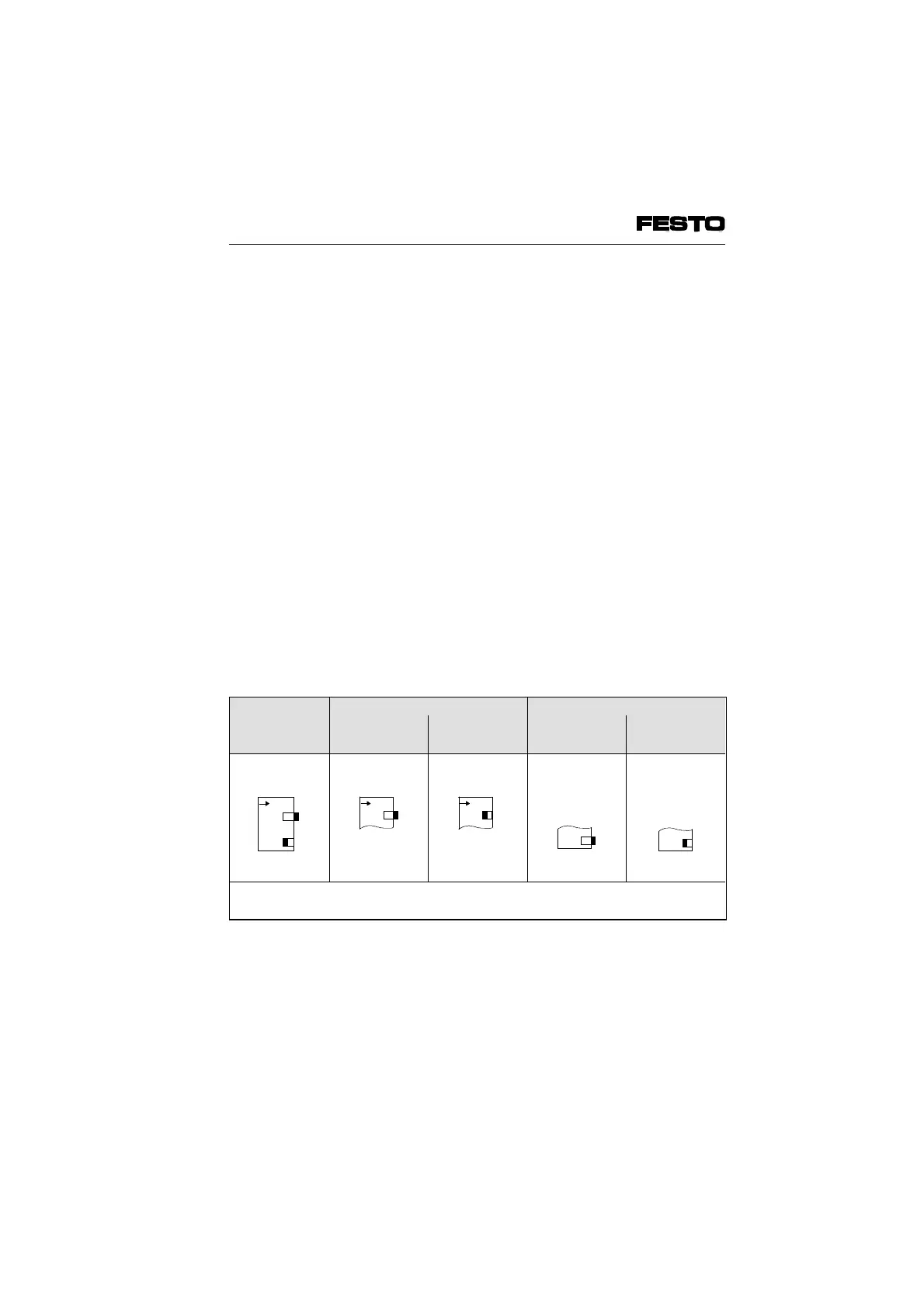
DIL-switch
(factory
setting)
Valve test Error messages
OFF ON
*)
Send part
**)
Send all
*)
Further instructions see Chapter 5.2
**)
Further instructions see Chapter 4.2
Fig 3/7: Position of the DIL switch elements
1
O
N
1
O
N
2
12
O
N
VIFB6 - 03/05 3. Installation
9809c 3-19