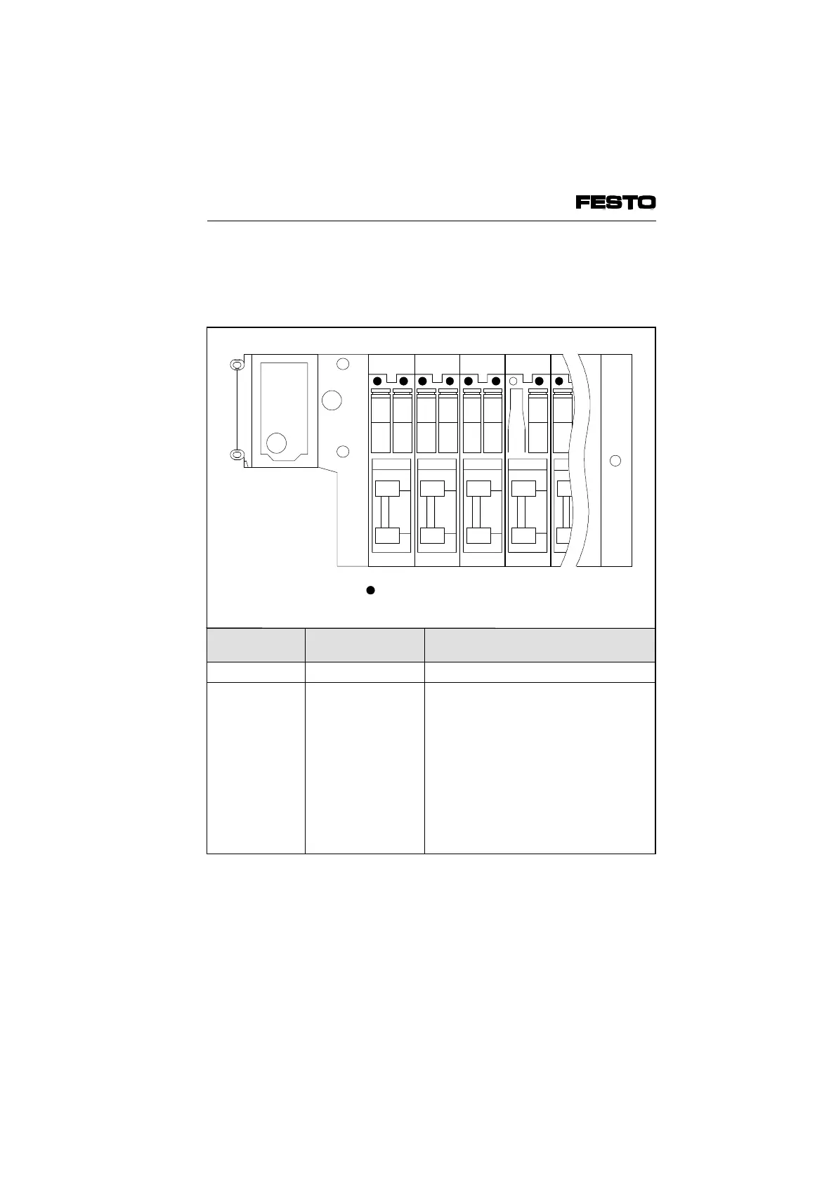
There is a yellow LED for each pilot solenoid
coil. This LED shows the switching status of the
pilot solenoid coil.
LED Switch position
Valve solenoid coil
Meaning
Yellow off Basic position Logic 0 (no signal)
Yellow alight • switch position
or
• basic position
Logic 1 (signal applied)
Logic 1 but:
• Operating voltage of outputs is below
permitted tolerance range
(DC 21.6V...26.4V)
or
• compressed air supply not correct
or
• pilot exhaust blocked
or
• call servicing personnel
12
14
12
14
12
14
12
14
Yellow LEDs
Fig. 5/5: LED displays – switching of ISO pilot solenoid coil type 05
VIFB6 - 03/05 5. Diagnosis/Error Treatment
5-8
9809c
 Loading...


