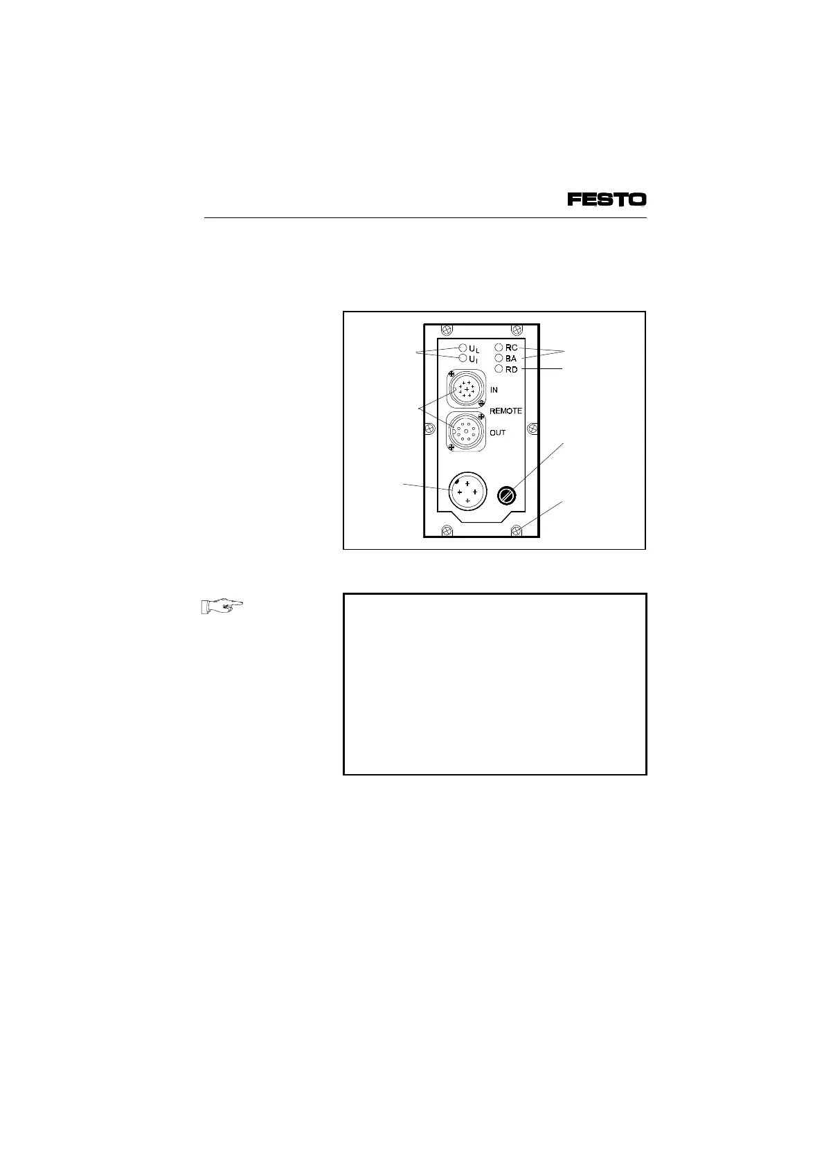
The following connection and display elements
are to be found on the cover of the node:
PLEASE NOTE
•
The cover need not be opened for normal
commissioning.
•
The cover is connected to the internal
printed circuit boards by means of the
operating voltage cable and cannot therefore
be removed completely.
•
If you wish to remote the cover, you must
unscrew both the 6 Philips screws in the
cover and 4 Philips screws of the bus plug.
Green LED
INTERBUS
interface
Fuse for
operating
voltage of
inputs
Power
supply
connection
Fig. 3/5: Cover of node
VIFB6 - 03/05 3. Installation
3-16
9809c