The following components of valve terminal type
03 are supplied separately with +24 V DC via
this connection:
• The operating voltage for internal electronic
components and the inputs of the input
modules
(pin 1: DC + 24 V, tolerance ± 25 %).
• The operating voltage for the valves outputs
and the outputs of the output modules
(pin 2: DC + 24 V, tolerance ± 10 %, external
fuse max. 10 A required).
PLEASE NOTE
Check your EMERGENCY STOP circuitry, to
see which measures are required in order to
place your machine/system in a safe state in
the event of an EMERGENCY STOP (e.g.
switching off the power supply to the valves
and output modules, switching off the com-
pressed air supply).
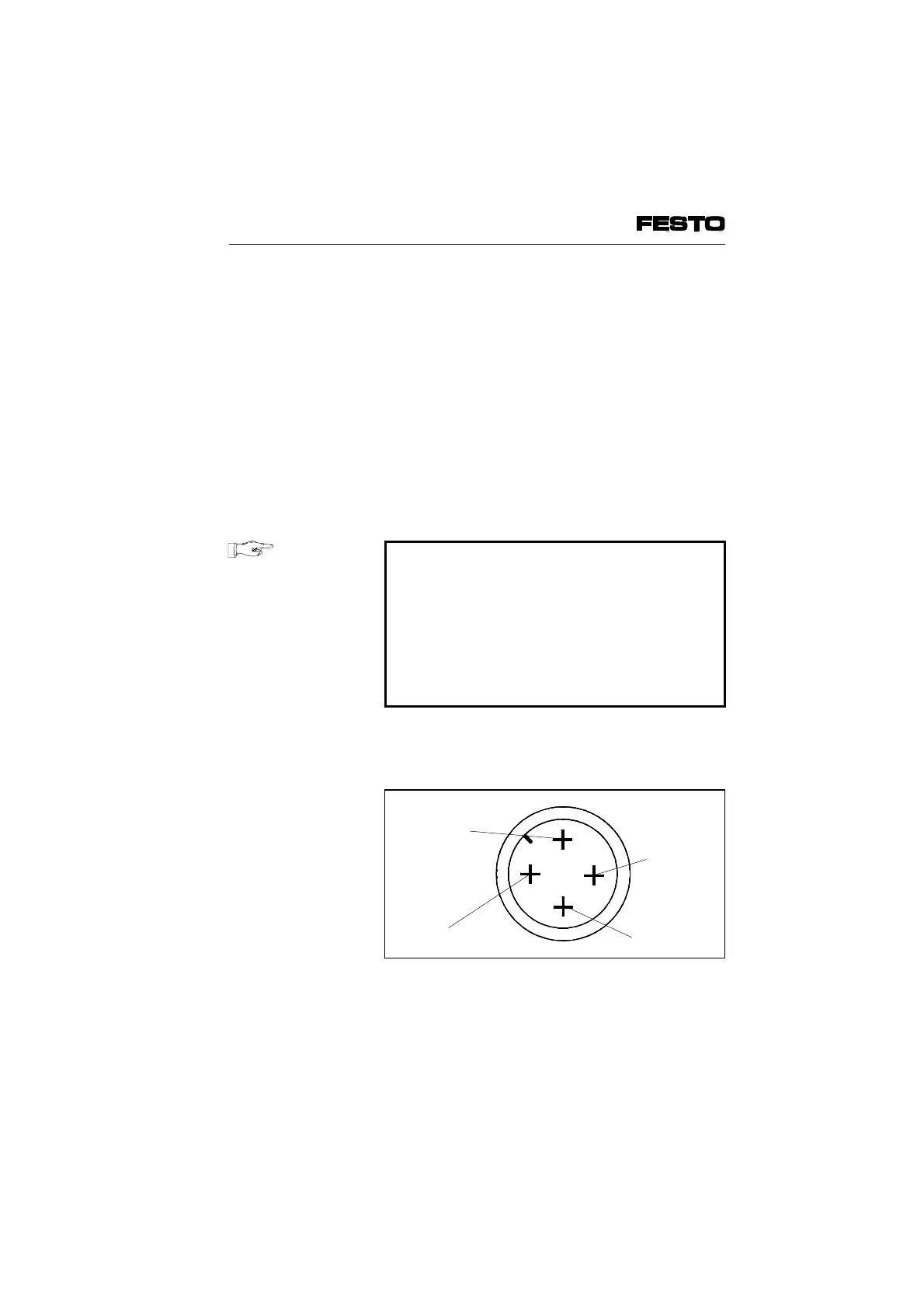
The diagram below shows the pin assignment of
the operating voltage connection.
0 VEarth connection
24 V
Supply for
electronic
components
and inputs
4
1
24 V supply
valves/outputs
Fig. 3/10: Pin assignment of the operating
voltage connection (type 03)
VIFB6 - 03/05 3. Installation
3-24
9809c