1. S ystem summary
1-10
Festo P.BE-CB-COMP-EN en 1102d
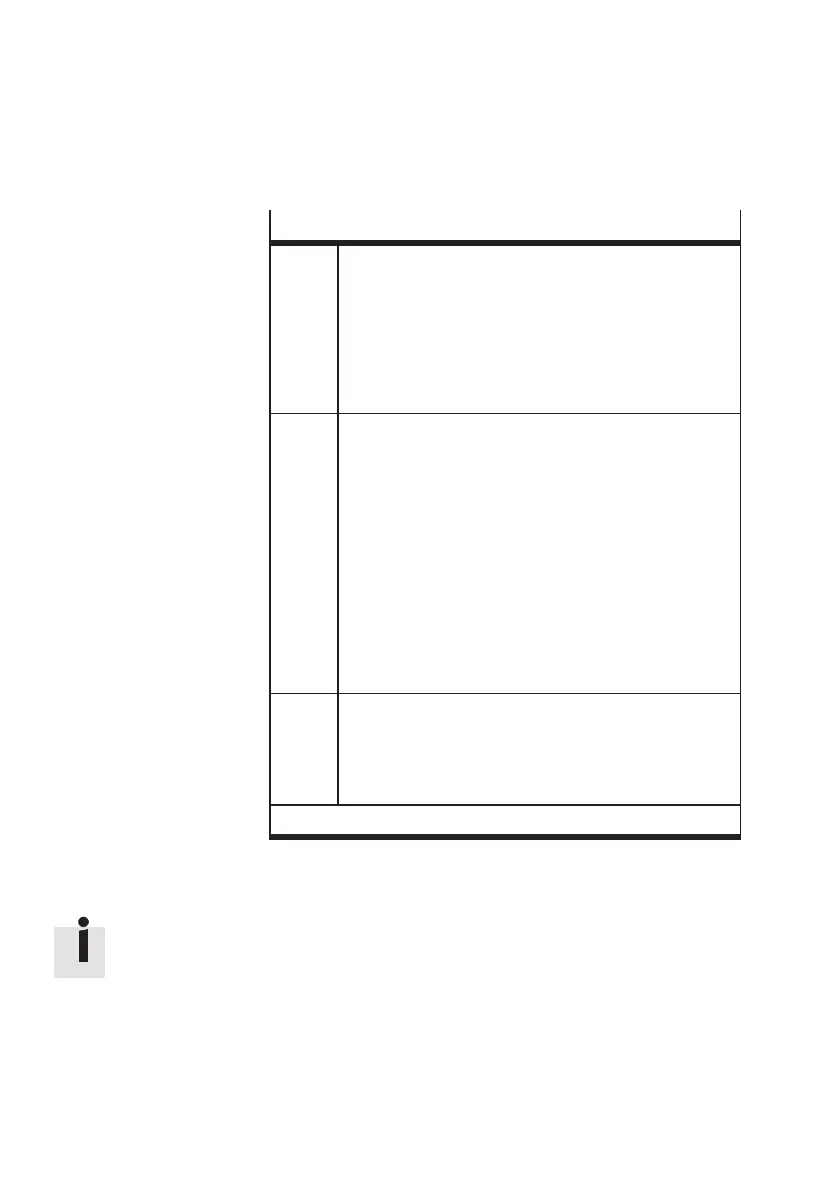
Dimensioning the buffer zone
A Section between the transpor t ing device and the sensor.
Section A must accept all conveyed parts which lie
between the Checkbox and the sensor when a conveyed
part has been registered by the sensor. The length
depends on:
– the geometry of the conveyed par ts
– the maximum feeder rate of the small parts conveyor
– the length of the transporting device
B Section between the sensor and the next machine
When the small parts conveyor is switched on again,
unint errupted operation of the assembly system must be
guaranteed until the first new conveyed part s arrive.
Section B must be designed so that a sufficient number of
conveyed par ts can be made available. The length
depends on:
– the geometry of the conveyed par ts
– the maximum time delay between switching on the
small parts conveyor again and making the new
conveyed par ts available
– the length and speed of the transporting device
– the average feed amount of good part s in the nominal
orientation.
AB *
)
Section between sensors 1 and 2 (Fig. 1/3).
Section AB determines the switching delay (hysteresis)
of the small parts conveyor for regulating the supply of
parts. The longer the section is, the less the switching
frequency.
*
)
Set the “Number of buffer zone sensors = 2” with CheckKon
Tab. 1/3: Buffer zone sections
Also observe Chapter 3.3 and Chapter 3.6.6 when connecting
the buffer zone sensors.