2 Assembly instructions
12 © Festo Didactic 759614
2.1.4 Mitsubishi
– Assembly:
The controller is assembled by engaging it on the H-rail (EN 50022).
– Disassembly:
The controller is disassembled by lifting the quick fastener using a screwdriver and removing the
controller from the rail.
Note
Further information on assembling or disassembling the controller or individual extension modules
can be found in the manuals of the respective controller manufacturers.
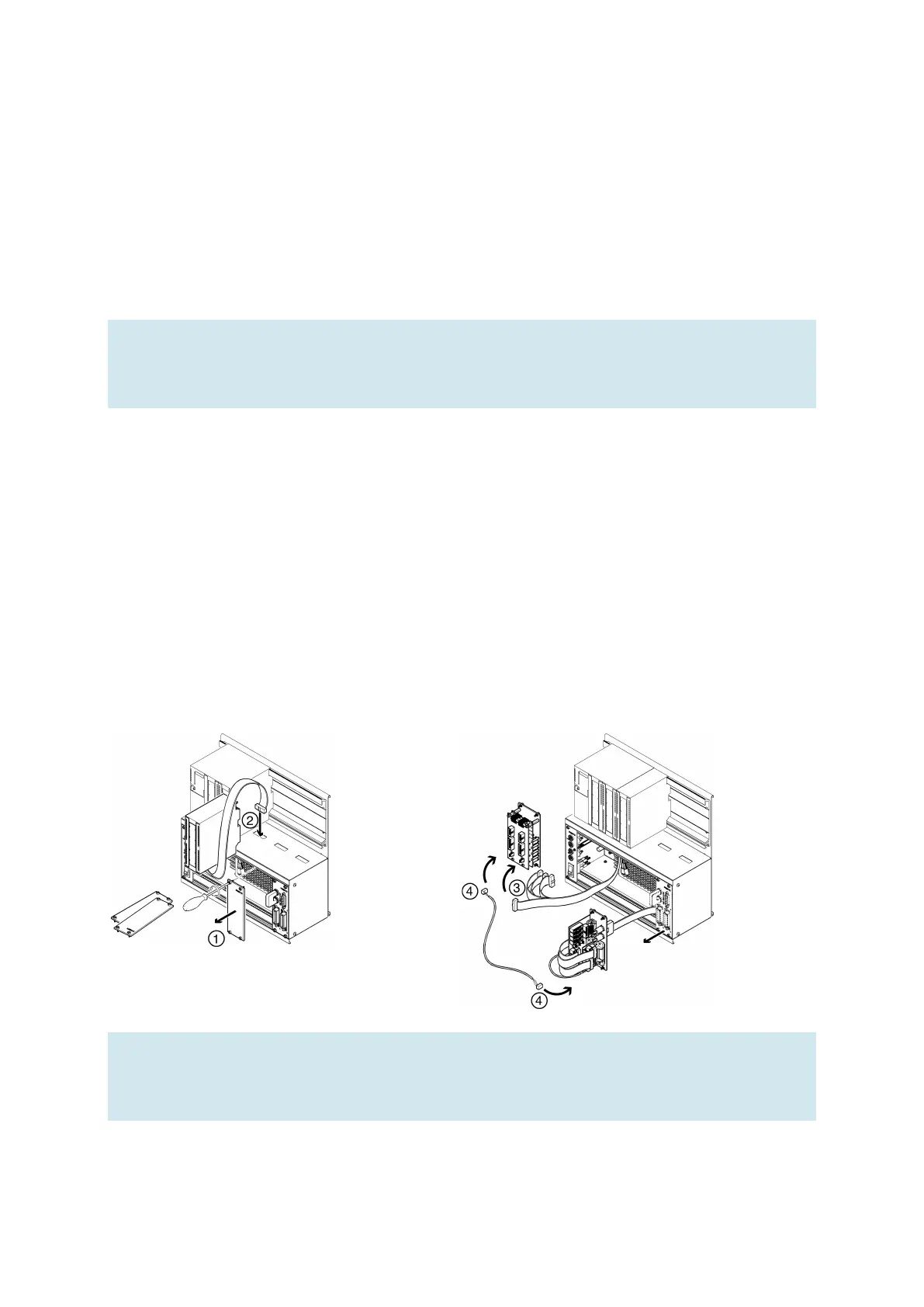
2.2 Extension with additional inputs/outputs
The installation process is shown using a Siemens controller as an example. This process is essentially the
same for all controllers; the only difference is how the controller is mounted on the holder system.
1. Remove as many blanking plates as necessary.
2. Guide the flat cable of the new I/O module through the cable entry into the housing and assemble the
module.
3. Connect the flat cables with the chosen 19-inch module.
4. To do this, connect the new 19-inch module with the last 19-inch module connected (e.g. SysLink
system connector module) via the 3-pin 24 V power supply cable.
Note
Unused slots must be covered with 19" blanking plates. Unused cable entries must be covered with
the covers included with the holder system.