15 19-inch AS-interface module
48 © Festo Didactic 759614
15.2 Commissioning
1. Connect the 0 V and 24 V screw terminals to the EduTrainer power supply module via the ring cable lugs
and wire end sleeves with the help of the blue and red cables.
2. Connect the protective earth screw terminal to the protective earth terminal on the EduTrainer housing
with the green-yellow wire (ring cable lug and wire end sleeve).
3. Connect the vacant ASI+ and ASI- screw terminals to the ASI+ and ASI- terminals on the AS-interface
controller module via the yellow AS-interface cable (wire end sleeves).
4. Screw the 19-inch module into the frame.
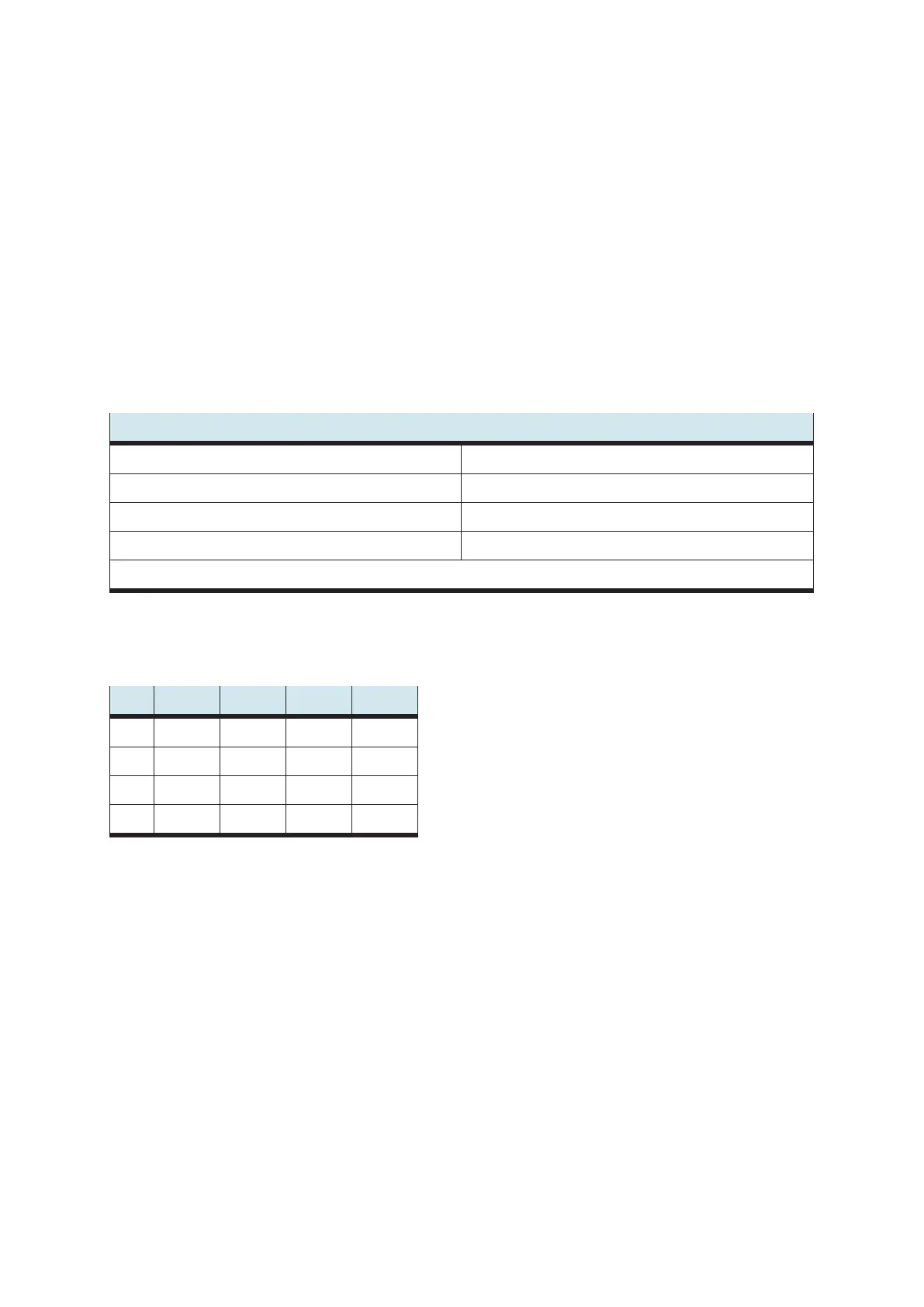
15.3 Technical data
Electrical / mechanical
Operating voltage 24 V DC ± 3%
AS-interface voltage 24 V DC ± 3%
Connection M12 AS-interface socket
Front panel width 6 HP
Subject to change
15.4 Pin allocation table
Pin M12 x 1
1 ASI+
2
3 ASI-
4