5 19-inch module 16DOUT
22 © Festo Didactic 759614
5.2 Commissioning
1. Connect the inputs/outputs to the PLC using a flat cable:
– SV3/SV4: Siemens S7 (16-pin)
– SV1/SV2: Other controller types (10-pin)
2. If using modules in parallel, these can be connected via the free insulation-displacement connector
SV1/SV2 or SV3/SV4 using flat cables.
3. Connect the 24 V power supply by means of the 3-pin connector SL1 or SL2.
4. Use the jumper JP1 or JP2 to define whether the output module is supplied directly via 24 V or via
24 V NA. 24 V NA is switched off in the event of an EMERGENCY-STOP.
– Jumper between pins 1 and 2: supply via 24 V.
– Jumper between pins 2 and 3: supply via 24 V NA.
5. Screw the 19-inch module into the frame.
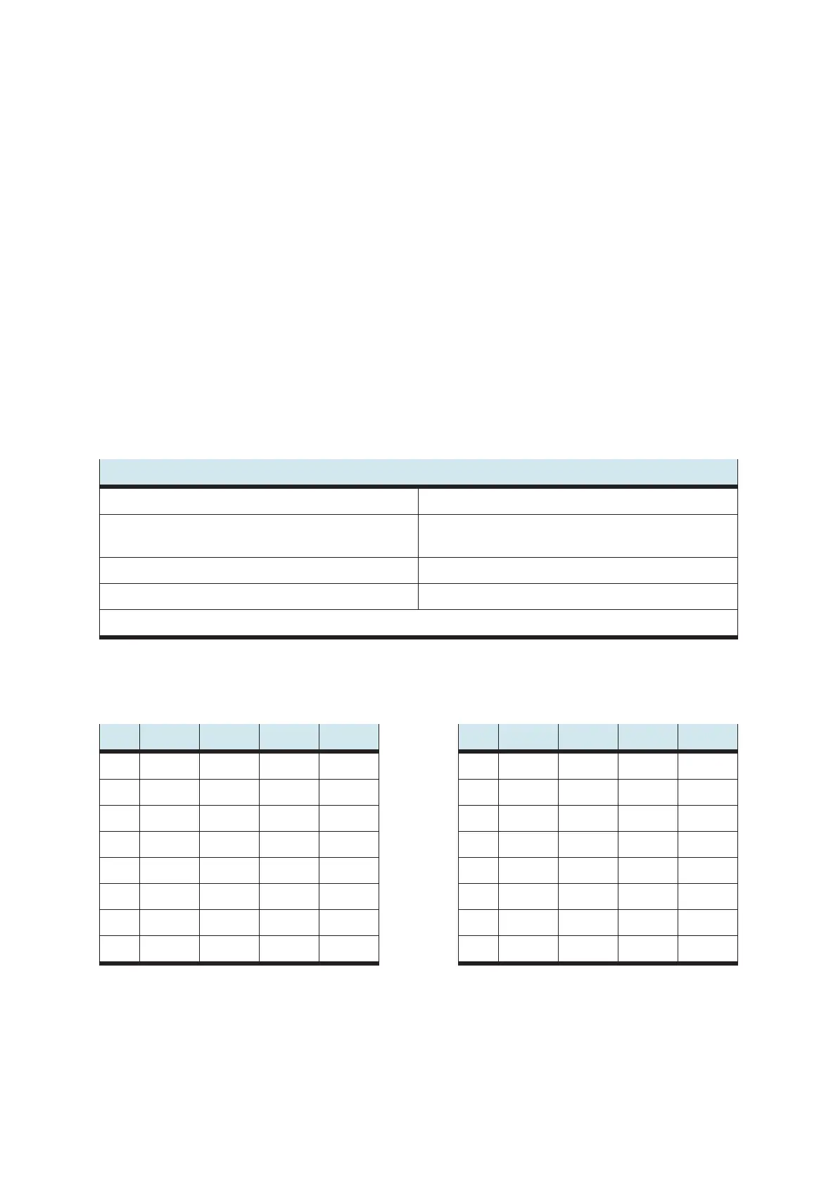
5.3 Technical data
Electrical/Mechanical
Operating voltage 24 V DC
Output current
Module: max. 0.5 A per output
PLC: see PLC manual
Connection 4 mm safety sockets
Front-plate width 12 HP
Subject to change
5.4 Contact allocation table
Pin SV1 SV2 SV3 SV4 Pin SV1 SV2 SV3 SV4
1 L1+ L2+ 0V 0V 9 Q7 Q17 L1+ L2+
2 Q0 Q10 Q7 Q17 10 0V 0V Q3 Q13
3 Q1 Q11 0V 0V 11 — — L1+ L2+
4 Q2 Q12 Q6 Q16 12 — — Q2 Q12
5 Q3 Q13 0V 0V 13 — — L1+ L2+
6 Q4 Q14 Q5 Q15 14 — — Q1 Q11
7 Q5 Q15 0V 0V 15 — — L1+ L2+
8 Q6 Q16 Q4 Q14 16 — — Q0 Q10