B. Supplementary component summary
B-16
Festo P .BE-MPA-EN en 1108e
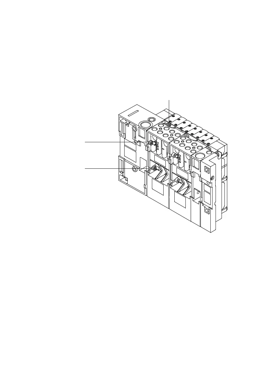
4. Insert the retaining screws in the appropriate holes.
Tighten the screws in the sequence 123
(see following diagram) at first slightly and then with
1.8Nm(±10%).
2
1
3
Fig. B/4: Fastening the MPA-S valve terminal to the
pneumatic interface
5. Fasten the MP A-S valve terminal onto the fastening
surface (see CPX system manual).
6. Complete the electrical and pneumatic connections of the
MPA-S valve terminal with CPX terminal. Information on
this can be found
– in the electrical section of the CPX system description
– inthepneumaticssectioninChapter3ofthismanual
 Loading...


