1. Summary of components
1-38
Festo P .BE-MPA-EN en 1108e
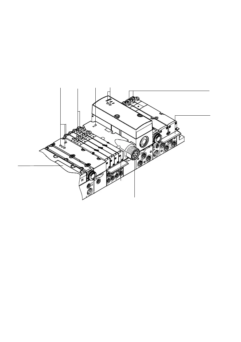
Y ou will find the following electric connecting and display
elements on the pneumatic components of the MPA-S valve
terminal with CPX terminal or CPI interface:
1
23
4
6
5
1
3
1
Inscription fields
2 Optional pressure sensor
(only for MPA-S with CPX terminal):
L EDs of the pressure sensor
see Fig. 1/19
3 LEDs on the valve: on the MP A1 a dual
colour LED/valve; on the MP A2 two
LEDs/valve:
yellow: Signal status display
of the pilot solenoids
red: Error displ a y
4 Optional additional electrical
supply:
Green power LED
5 Optional LED/LCD
proportional-pressure regulator
(only for MPA-S with CPX terminal):
LEDs/LCD of the proportional-
pressure regulator see Fig. 1/20 or
Fig. 1/21
6 Optional additional electrical
supply:
V alve load voltage connection
Fig. 1/18: Electric connecting and display elements of the MP A-S valve terminal with CPX
terminal or CPI module