NFPA Standard-Specific Requirements Correlations
152 MS-9600 PN 51335:E 7/9/03
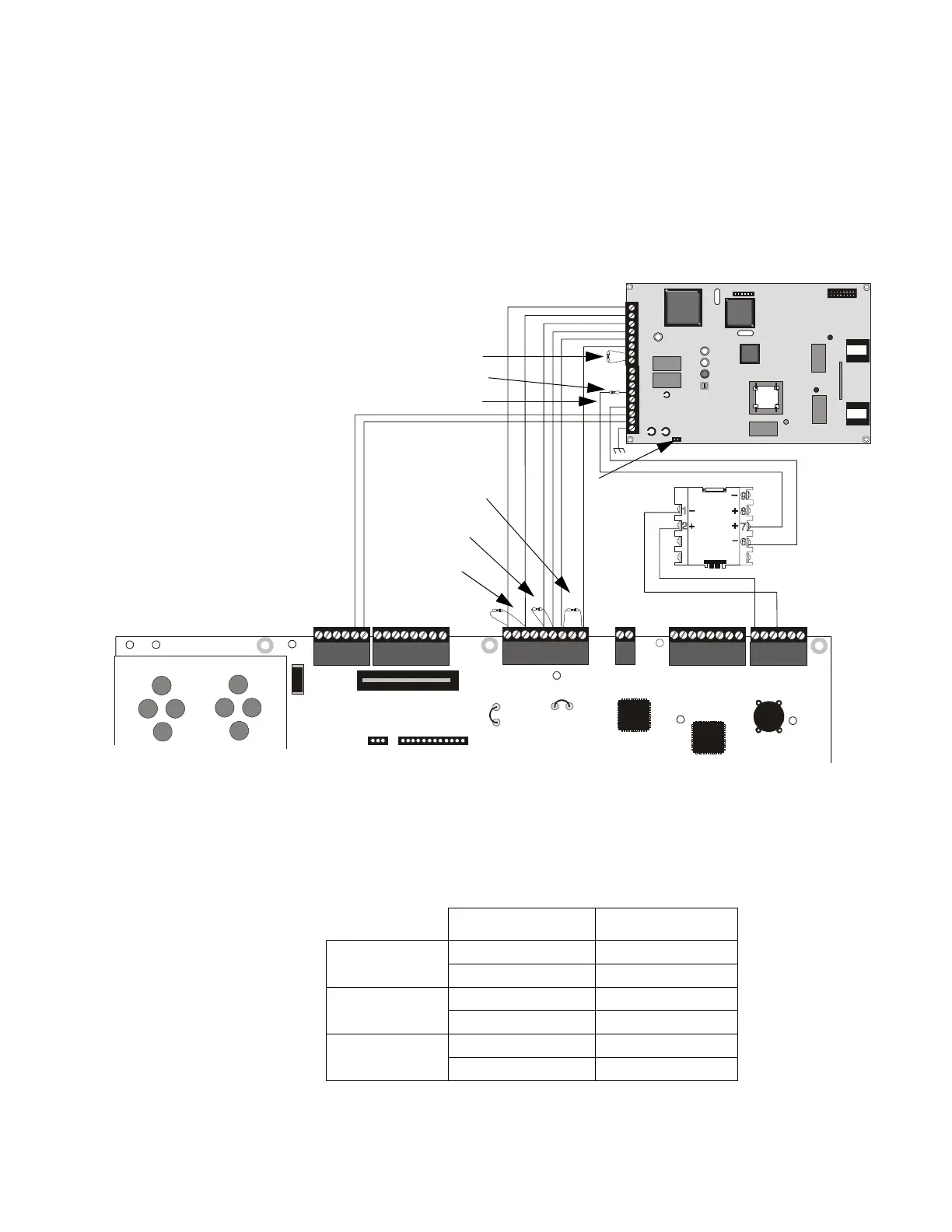
The following figure illustrates an example of Central Station/Remote Station Reporting using a
411UD. The relay contacts from the MS-9600 may be used to trip any dialer UL listed for Central
Station/Remote Station Reporting Services.
TB2
TB1
U8
U10
U11
J1
J2
J4
PH1
R41
PH2
Monitor
Module
TB3
JP3
JP5
JP6
JP8
J10
J11
REMOVE TO
DISABLE
LOCAL
CHARGER
CUT TO
MONITOR 4XTM
4XTM OPT BD
TB4
TB5
TB6 TB7
TB8
Figure C.3 Fire•Lite MS-9600 Connection to 411UD
Note: The Monitor Module input, which is being used to
monitor the 411UD Relay #2 Output (programmed for
DACT Trouble), must be programmed as ‘Trouble’ at
Fire•Lite MS-9600.
Channel1
Channel 2
Channel 3
Channel 4 (2.2K EOL)
Relay Output (DACT Trouble)
Monitor Module EOL resistor
24 VDC nonresettable power
MS-9600
Supervisory Relay
MS-9600
Alarm Relay
MS-9600
Trouble Relay
(2.2K EOLS
P/N 27070)
J4 Not Installed
411UD
Monitor Module
Circuit Input
SLC Loop
+
_
Fire•Lite MS-9600
9600411u.cdr
24 VDC nonresettable power
1 2 3 4 5 6 7 8 9
1
2
3
4
5
6
7
8
1
2
3
4
5
6
7
8
411UD MS-9600
Alarm TB2-1 TB5-1
TB2-2 TB5-3
Trouble TB2-3 TB5-5
TB2-4 TB5-6
Supervisory TB2-5 TB5-7
TB2-6 TB5-9
Table C.2 411-UD Connections to MS-9600