Installation Optional Modules and Devices
34 MS-9600 PN 51335:E 7/9/03
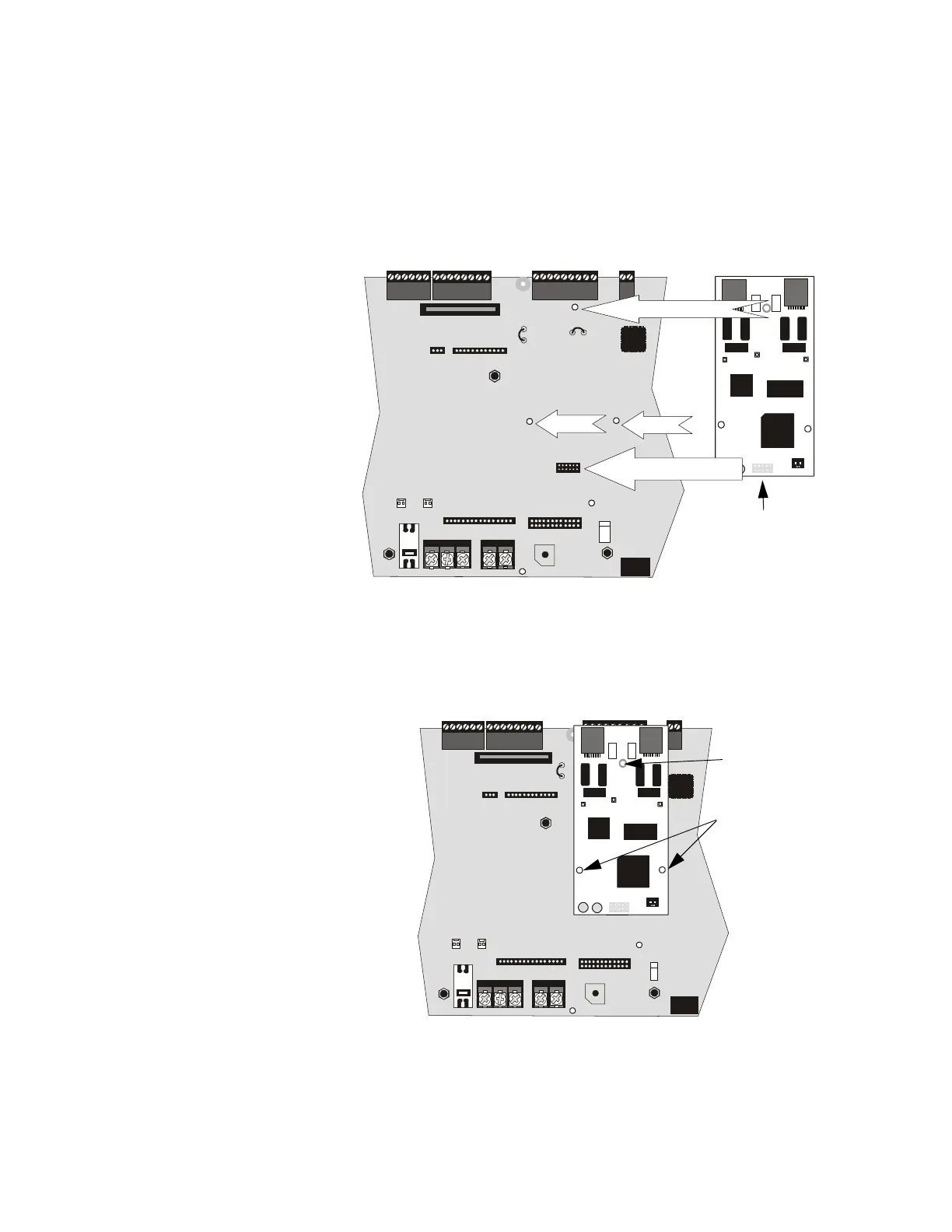
The following steps must be followed when installing the DACT module:
1. Remove all power (AC and DC) from FACP before proceeding with installation
2. Remove the Keypad/Display from the main circuit board as described in the
beginning of this section
3. Carefully plug connector J1 on back of the DACT-UD module into connector J2
on the MS-9600 main circuit board, being careful not to bend any pins
4. Align the mounting holes in the DACT module with the premounted standoffs on
the FACP main circuit board
5. Secure the module to the standoffs on the main circuit board with the three
screws supplied with the DACT-UD. It is important that the supplied screws be
used to secure the module to the metal standoff in order to help protect against
electrical transients.
6. Reinstall Keypad/Display on the main circuit board by positioning the unit over
the appropriate standoffs and securing with screws which were loosened in step 2
7. Make certain to program the control panel for DACT operation
J1
J2
J3
SECONDARY
PRIMA RY
SW1
O
F
F
O
N
2 1
+ BATTERY-
LCD DISPLAY
KEYPAD I/F
OPT DACT
HOT
CB1
J2
TB1
TB2
SW1
JP5
JP6
J17
J16
J6
J8
J7
J10
J11
CU T TO
MONITOR 4XTM
4XTM OPT BD
TB4
TB3
TB5
JP8
TB6 TB7
NEUT E ARTH
Figure 2.12 DACT J1 Connector to FACP J2 Connector
J1J2
Standoff
Standoff
Standoff
J1 Connector located on
back of DACT module
+ BATTERY-
LCD DISPLAY
KEYPAD I/F
OPT DACT
HOT
CB1
J2
TB1
TB2
SW1
JP5
JP6
J17
J16
J6
J8
J7
J10
J11
CU T TO
DISAB LE
SPV RELAY
CUT TO
MONITOR 4XTM
4XTM OPT BD
TB4TB3 TB5
TB6
NEUT EARTH
JP8
J1
J2
J3
SECONDARY
PRIMARY
SW1
O
F
F
O
N
2 1
Figure 2.13 DACT Installation on Standoffs
Mounting Screw
Mounting Screws