TOTALPAC2 Page 1 of 2
TOTALPAC2 Integrated Fire Protection System
Trim Options
FM-086G-0-46C
1. Shut-Off Valve & Sight Glass:
The Shut-off Valve & Sight Glass Option is intended to be
used for applications where testing of the system operation
without filling the sprinkler piping network is desirable and
where it is critical that all functions of the preaction system be
tested under actual discharge conditions. Examples of such
applications are freezers, ovens, museums, data processing
and other hazards where the possibility of water leaking from
the piping system is to be avoided at all costs.
Operation of the shut-off valve: Inspection of the system
can be implemented without filling the sprinkler piping system
with water.
.1 CLOSE the Supervised sprinkler piping system Shut-Off
Valve (D4); the valve is supervised on the same circuit
as the system Water Supply Control Valve (D1).
.2 OPEN the system Main Drain Valve (D3).
.3 Simulate the operation of the system to open the Deluge
(A1) or Flow Control Valve (A2) (See Annual test under
the INSPECTION AND MAINTENANCE section.) Using
a flashlight in one of the sight glasses, verify that water
flows through the Sight Glass Assembly (D5).
.4 Once tests are completed, make sure the system Main
Drain Valve (D3) is completely CLOSED. Reset the
system as per PLACING THE SYSTEM BACK IN
SERVICE.
.5 FULLY OPEN the system Shut-Off Valve (D4). Reset
the system's Release Control Panel.
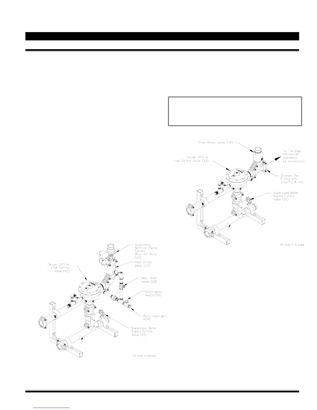
Figure 1 - Test Valve for Preaction Systems
2. Fire Department Connection:
The Fire Department Connection Option consists of a
grooved Tee fitting installed in lieu of the 90 degree elbow at
the outlet of the Deluge / Flow Control Valve (A1 or A2). An
access hole of the proper diameter is factory pre-drilled on
the side of the TotalPac enclosure for connection of the
piping going to the Fire Department Connection.
Note: The Fire Department Connection hardware itself
(drain, Siamese, etc.) is NOT provided with this option and
shall be provided by the installing contractor. Refer to
NFPA-13 Standard for additional information about the
equipment layout and installation.
Figure 2 – Fire Department Connection for Preaction
Systems: