Page 8 of 12 TOTALPAC2
TOTALPAC2 Integrated Fire Protection System
Deluge System - Programming & Field Wiring Diagram
FM-086G-0-38E
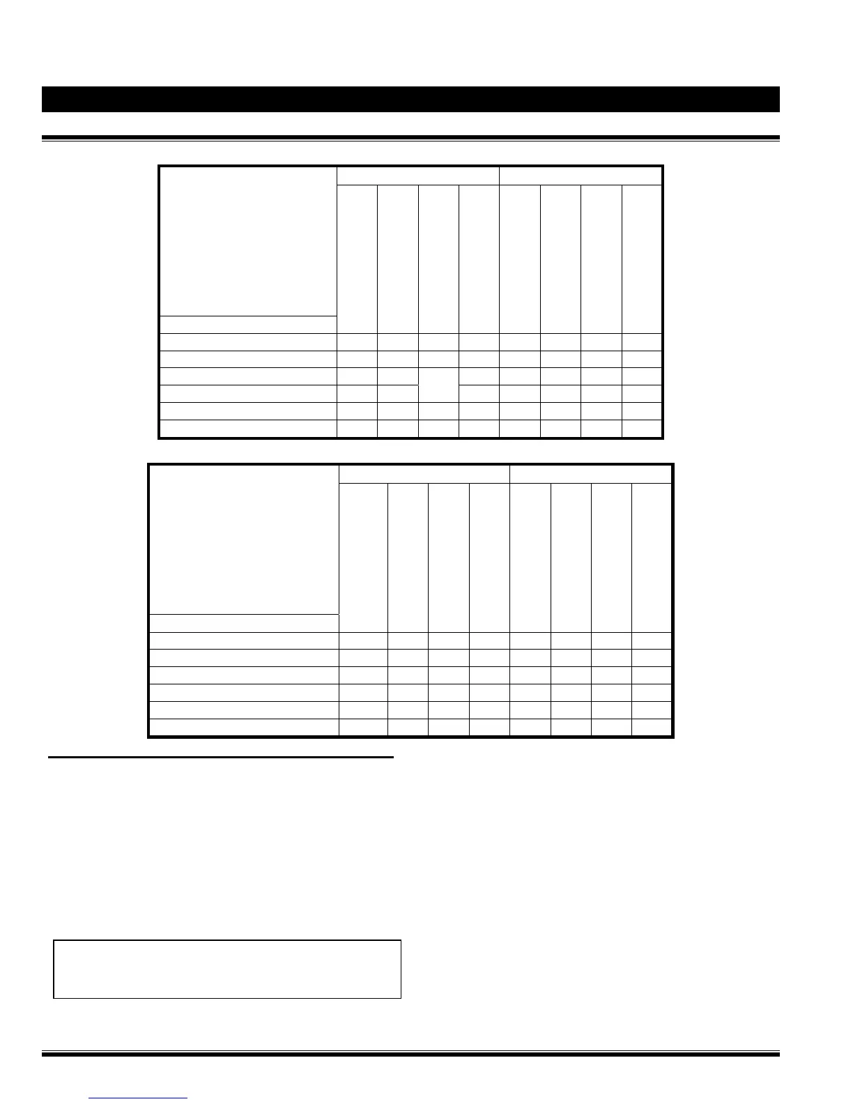
Program #12 Output and Relay Circuits Activated by Detection Circuits:
OUTPUT CIRCUITS RELAY CIRCUITS
PROGRAM 12
SINGLE HAZARD
CROSS ZONED
INPUT CIRCUITS
ALARM BELL
WATERFLOW BELL
RELEASE SOLENOID
SUPERVISORY BELL
ALARM RELAY
TROUBLE RELAY
WATERFLOW RELAY
SUPERVISORY RELAY
SUPERVISORY ZONE 1 (Valve Tamper) X
X
X
SUPERVISORY ZONE 2 (Air) X
X
X
DETECTION ZONE 1 X X
X
DETECTION ZONE 2 X
BOTH
X
X
DETECTION ZONE 3 (Waterflow) X X
X
X
DETECTION ZONE 4 (Pull Station) X X X
X
Program #5 Output and Relay Circuits Activated by Detection Circuits:
OUTPUT CIRCUITS RELAY CIRCUITS
PROGRAM 5
SINGLE HAZARD
TWO ZONES
NYC
INPUT CIRCUITS
ALARM BELL
SUPERVISORY BELL
RELEASE SOLENOID
TROUBLE BELL
ALARM RELAY
TROUBLE RELAY
WATERFLOW RELAY
SUPERVISORY RELAY
SUPERVISORY ZONE 1(Valve Tamper) X X
X
X
SUPERVISORY ZONE 2 (Supervisory) X X X X
DETECTION ZONE 1 (Detection) X X X X
X
DETECTION ZONE 2 (Supervisory) X X
X
X
DETECTION ZONE 3 (Waterflow) X X
X
X
DETECTION ZONE 4 (Pull Station) X X X X
X
Operation
When a fire occurs, at least one detector reaches its trip
point. One detection circuit is then automatically activated (in
crossed zones mode, both detection zones have to be
activated) OR the activation of Zone 4 (pull station). The
system alarm audible devices sound and, if desired, can be
silenced manually. The normally closed (N.C.) solenoid
valve of the system is energized, allowing the water to
escape from the priming chamber of the deluge valve. The
clapper of the deluge valve opens, filling the outlet chamber
and flooding the entire area covered by the sprinklers and
nozzles. System waterflow audible devices and the water
motor gong (if installed) will sound.
WARNING ! The sprinkler system will continue to
operate until the main water inlet valve is manually
closed.