T
OTAL
P
AC
2
Page 11 of 12
T
OTAL
P
AC
2 Integrated Fire Protection System
System design & Dimensional Data
FM-086G-0-48C
Configuration
System
Size
P S
1½"
34½" 41¾"
2"
34" 41¼"
3"
38⅜" 42⅛"
4"
39⅝" 44¼"
Preaction
6"
48⅝" 54½"
Figure 2 – Minimum cabinet & doors clearance detail
A
C
B
B
TotalPac2 Unit
FM-072Q-0-25 A.dwg
Unit Size Minimum Dimensions
A
1 ½"
2"
3"
4"
6"
52"
52"
52"
70"
70"
132 cm
132 cm
132 cm
178 cm
178 cm
B
All 12" 30,5 cm
C
All 24" 61 cm
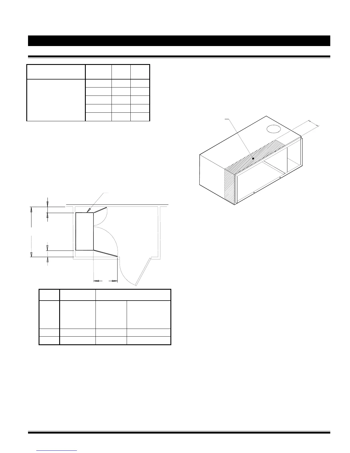
Drilling:
When drilling in the cabinet to install wiring conduits or pipes,
avoid the area of the front 6" (15 cm) of the top of the cabinet
since internal wiring is concentrated in that area. Always
avoid drilling into internal components.
Figure 3 – Drilling detail:
"NO DRILL" ZONE
6"
Note: Control cabinet shown without front door.
Hatch pattern indicates zone that should be
avoided when drilling for wiring conduits in enclosure,
viewed from the left front corner of the cabinet.
F
M
-
0
7
2
Q
-
0
-
6
3
A
.
d
w
g
Wiring Routing:
Wiring shown in Figure 4 below indicates typical Wiring
Routing for Power Limited Circuits.
Refer to FIELD WIRING DIAGRAM and drilling guide above
for details.