Page 4 of 12
T
OTAL
P
AC
2
T
OTAL
P
AC
2 Integrated Fire Protection System
System design & Dimensional Data
FM-086G-0-48C
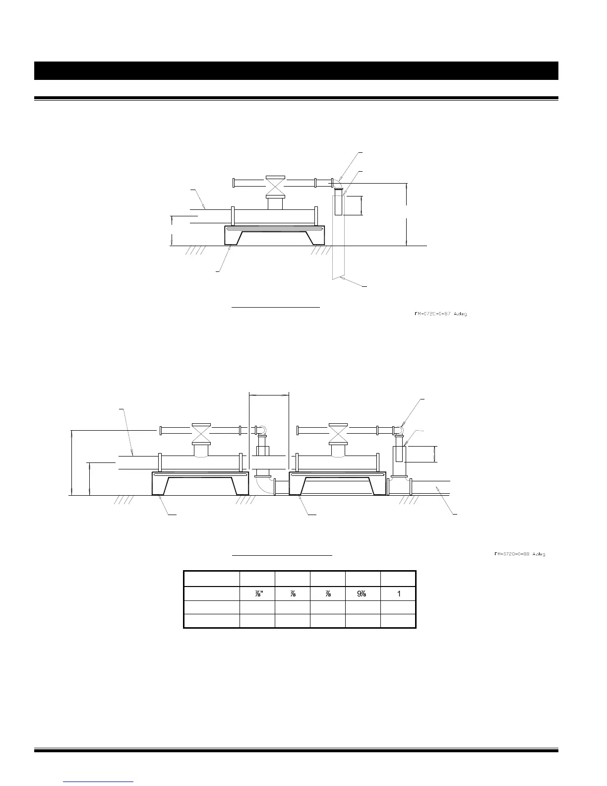
Figure 4: Open drain details for single unit:
(see dimensions in table below)
Drain Pipe (pipe diameter
per drain flow calculation)
Air Gap
Water Supply Pipe
Unit Drain Pipe
(dia. = C)
4" Min.
B
A
Single Unit Detail
TotalPac2 Skid Ass'y
Figure 5: Open drain details for multiple units:
(see dimensions in table below)
Drain Collector running
between wall and units
(pipe diameter per
drain flow calculations)
Typical Air Gap
Water Supply Pipe
(Can Be Manifolded)
Unit Drain Pipe
(dia. = C)
DO NOT MANIFOLD !
Multiple Units Detail
12" (Min.)
B
A
4" Min.
TotalPac2 Skid Ass'yTotalPac2 Skid Ass'y
Unit Size: 1½" 2" 3" 4" 6"
A
8
" 8
" 9
" 9
" 11"
B
18½" 18½" 18½"
18½"
18½"
C
2" 2" 2" 2" 2"
Notes:
1. Supply and drain pipes can be connected on either sides of cabinet.
2. All pipes and fittings should meet applicable codes.
3. Actual drain collector diameter shall be determined with detailed hydraulic calculations and is the responsibility of the system
designer.