TOTALPAC2 Page 7 of 12
TOTALPAC2 Integrated Fire Protection System
Deluge System - Programming & Field Wiring Diagram
FM-086G-0-38E
4- Self-Contained, Electric Release
The VIKING VFR-400 Control Panel included with the
T
OTALPAC2 Unit is factory programmed and wired for the
following configurations:
f Deluge, Electric Release
f Deluge, Electric Release NYC
and
f Activation by Zone 1 OR Zone 2
f Activation by Zone 1 (NYC)
f Activation by Zone 1 AND Zone 2 (Cross-zoned)
f Activation by Zone 4 (Pull Station) for all
configurations
This programming makes sure the system will perform as
required and was factory tested to make sure it meets all
requirements.
Pre-configured programs allows field programming for
possible input/output combinations, of which only three are
available and Listed for the current use of the T
OTALPAC2
System:
Program #1, Single Hazard, Two Alarm Zones with One
Manual Station Zone, One Waterflow Zone and
Two Supervisory Zones.
Program #12, Single Hazard, Two Alarm Zones (Cross-
Zoned) with One Manual Station Zone, One
Waterflow Zone and Two Supervisory Zones.
Program #5, Single Hazard, One Alarm Zone with One
Manual Station Zone, One Waterflow Zone and
Three Supervisory Zones. (NYC)
Program #1 allows the panel to activate the solenoid valve
when EITHER detection Zone 1, Zone 2 OR Zone 4 is
activated.
Program # 12 allows the panel to activate the solenoid valve
when BOTH detection Zone 1 AND Zone 2 are activated
(Cross-zoned) OR Zone 4 only. (Pull Station)
Program #5 allows the panel to activate the solenoid valve
when EITHER detection Zone 1 OR Zone 4 is activated.
WARNING ! Only the three Pre-configured programs
above are Listed/Approved with the present
TOTALPAC2 Unit. Changing for another pre-
configured program may eliminate the Fire
Protection capabilities of the system and/or void
Listing/Approval and Warranty. Consult FireFlex
Systems before making any change
Note: The control panel motherboard is factory pre-
wired and programmed for the configuration selected
at the time of purchase. All field wiring should be
terminated as shown on the FIELD WIRING
DIAGRAM.
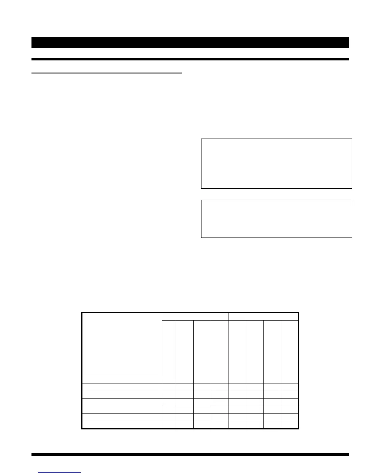
Program #1 Output and Relay Circuits Activated by Detection Circuits:
OUTPUT CIRCUITS RELAY CIRCUITS
PROGRAM 1
SINGLE HAZARD
TWO ZONES
INPUT CIRCUITS
ALARM BELL
WATERFLOW BELL
RELEASE SOLENOID
SUPERVISORY BELL
ALARM RELAY
TROUBLE RELAY
WATERFLOW RELAY
SUPERVISORY RELAY
SUPERVISORY ZONE 1 (Spare) X
X
X
SUPERVISORY ZONE 2 (Valve Tamper ) X
X
X
DETECTION ZONE 1 X X X
X
DETECTION ZONE 2 X X X
X
DETECTION ZONE 3 (Waterflow) X X X
X
X
DETECTION ZONE 4 (Pull Station) X X X
X