Page 2 of 14
T
OTAL
P
AC
2
T
OTAL
P
AC
2 Integrated Fire Protection System
Air Supply
FM-086G-0-43E
1.2 Connecting the Air Compressor to AC power
The motor must be protected against short circuit, overload
and excessive temperature rise. Fuses, motor protective
switches and thermal protective switches provide the
necessary protection in these circumstances.
Fuses only serve as a short circuit protection of the motor
(wiring fault), not as protection against overload. Those are
provided and wired by the electrical contractor. An isolation
switch (for location detail, refer to Figure 2 in CONTROLS
Section) is also provided in the T
OTAL
P
AC
2 Cabinet and is
factory wired, allowing powering off the air compressor while
some maintenance work on the unit is done, without
disturbing the rest of the system.
Connect non-energized AC power to the air compressor.
Refer to figure below and FIELD WIRING DIAGRAM.
4
2
1
TBB
NEUTRAL
GROUND
L1
AIR COMPRESSOR
1 HP Maximum
120Vac, 60Hz 220Vac, 50 Hz
Wiring size: Minimum 14 AWG with 600V Insulation.
Wiring of 120/220Vac Air Compressor
Power Source
INPUT POWER SOURCE
Branch circuit for air compressor shall not be the same
as the control panel power source
!
3
COMPRESSOR Amp rating
Compressor Size
(HP)
Amp. Rating at
120Vac – 60Hz
Amp. Rating at
220Vac – 50Hz
1/6 6.8 A 2.8 A
1/3 6.5 A 3.5 A
1/2 8 A 4.8 A
1 12.4 A 7.6 A
1.3 Operation
Air Supply Style "A":
1.3.1 To Apply Air Supply:
Establish AC power for the air compressor by activating the
correspondent circuit breaker at the electrical distribution
panel. Start compressor by activating the
compressor
isolating switch (E15) located in the control section of the unit
(refer to CONTROL SECTION, Fig. 2 for exact location of the
isolating switch).
If the air compressor motor fails to start or slows down under
load, shut the compressor off. Check that the supply voltage
agrees with the motor nameplate.
A Float Check Valve (E9) is provided with Air Option "A".
The Float Check Valve allows sensing of air pressure in the
system during supervisory times of the system.
1.3.2 To close air supply:
Turn off the compressor isolating switch (E15).
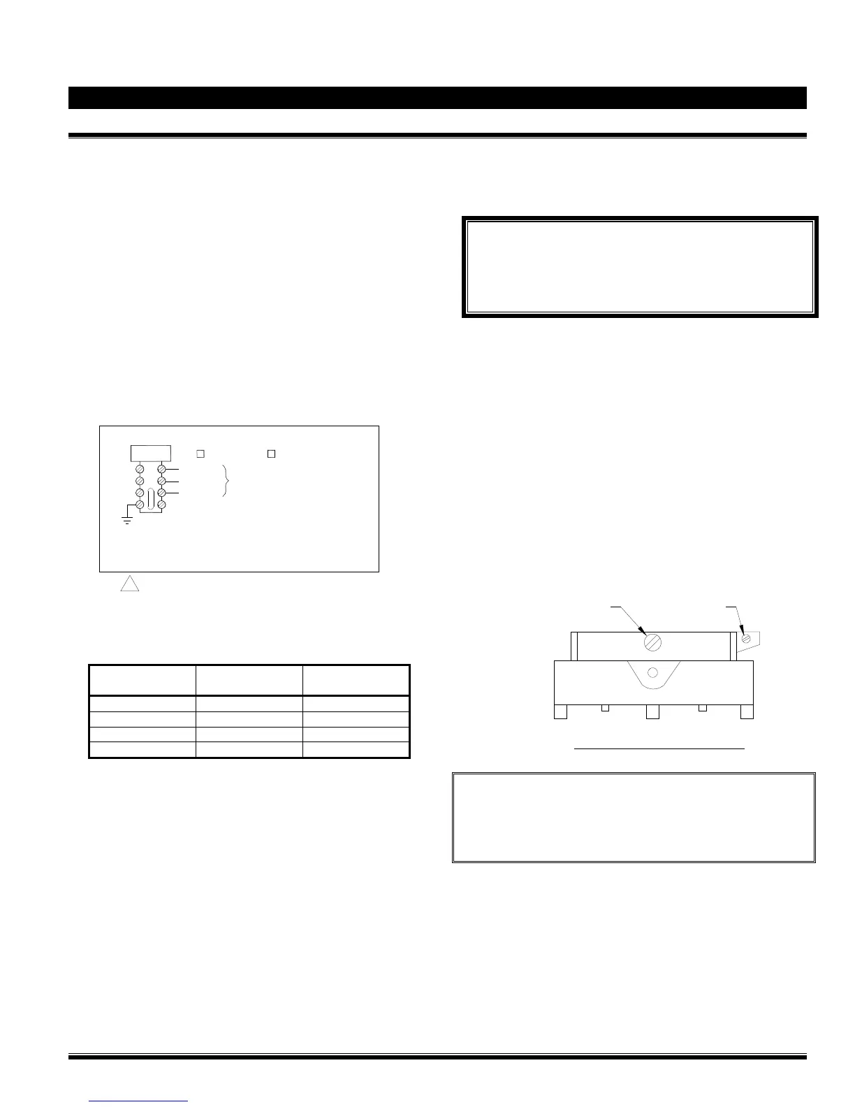
1.3.3 To adjust system air pressure (Furnas switch):
WARNING ! The cut-out/cut-in differential switch
adjustment screw (small screw to the right) is factory set.
DO NOT CHANGE ITS SETTING. Any unauthorised
modification of this setscrew adjustment will void the
system warranty and may also prevent the system from
operating normally.
The air compressor cut-off pressure switch (E2) (shown
below with its metal cover removed) has its air compressor
cut-out adjustment switch (middle screw) factory set. This
switch should not need any adjustment but if necessary,
follow the instructions below:
a) Remove the metal cover of the compressor air
pressure switch (E2).
b) To raise the cut-out pressure of the air compressor,
turn the cut-out adjustment screw (middle) half a
turn CLOCKWISE.
c) Open the system main drain valve (D3) and let the
pressure drop until the air compressor (E1) restarts.
Check pressure reading on the system pressure
gauge (E3) when the air compressor stops again.
Repeat until the desired pressure is reached. Once
all done, replace the metal cover on the switch (E2).
Turn clockwise to increase
both cut-out and cut-in
pressure adjustment.
Factory set.
DO NOT CHANGE !
Front view of the Furnass Switch
(Part # 69HA3)
FM-072Q-0-109 A
Note: Do not turn the cut-out adjustment screw (middle)
all the way down in one shot. Proceed by steps.
Use the same method turning the cut-out
adjustment screw COUNTER-CLOCKWISE to
lower the air compressor cut-out pressure.