TOTALPAC2 Page 3 of 8
TOTALPAC2 Integrated Fire Protection System
Control Section
FM-086G-0-29C
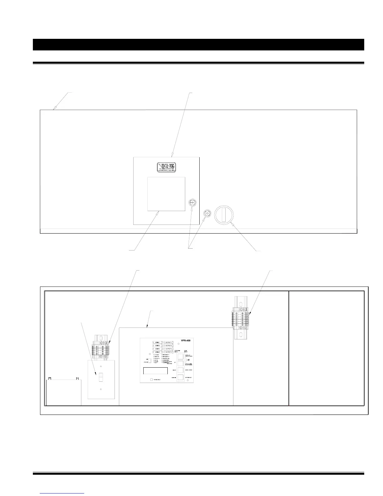
Figure 1 - Cabinet door assembly:
Control section hinged door
(recessed hinges on top)
Releasing panel controls
access door (stainless steel)
Control Panel
annunciator window
Door Lock
(with key alike keys)
Flush door handle
FM-086V-0-19
FM-086V-0-20
Typical control panel
motherboard placement.
"TBC" field terminal strip
for Los Angeles & Chicago option
"TBB" field terminal strip
for 120 / 220 Vac Power Supply
(under protective cover)
Emergency
batteries
Air compressor
isolatin switch (E15)
NOTE: TBB field terminal strip and Air compressor isolation switch (E15) only with Air Supply Style A air
Figure 2 - Control equipment layout: