Page 10 of 12 TOTALPAC2
TOTALPAC2 Integrated Fire Protection System
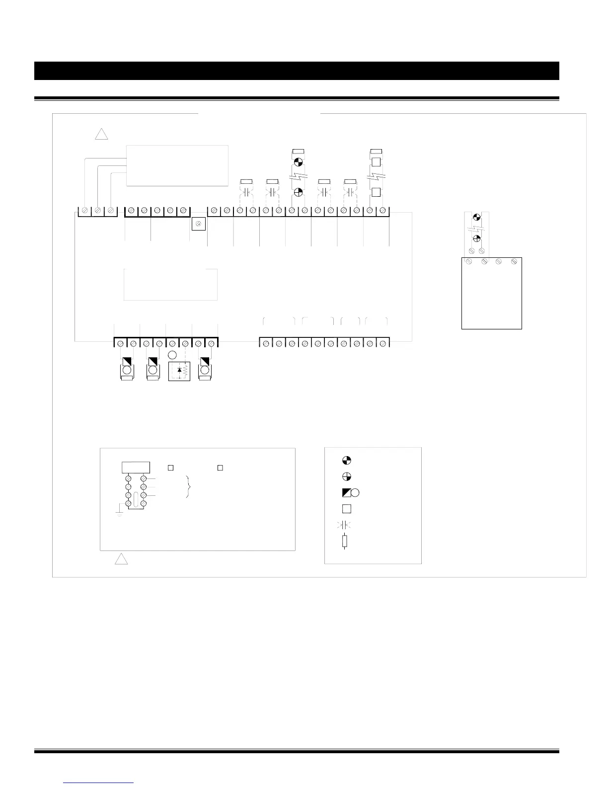
Deluge System - Programming & Field Wiring Diagram
FM-086G-0-38E
ZONE 1
-
+
-
+
-+ -+
+-
ZONE 2
Wiring in Class A (style D)
Included CA2Z will
convert Zone 1 & Zone 2
Class-B Zones into two
Class-A Zones
Note: ELR, are not
required on Class-A
Program #5 / Factory pre-wired Zones:
SUP.1=Valve Tamper
SUP.2=Low Air (n/a on Deluge)
ZONE 2=Low Air Alarm (n/a on Deluge)
ZONE 3=Waterflow
OUT 3=Releasing Solenoid
Input Wiring in Class B (style B)
+
-
+
-
+
-
SUP.2SUP.1
AUX.
POWER
24VR DC
TB101
TB103
COM
NO
COM
NO
COM
NO
NC
COM
NO
NC
TROUBLE
ALARM
SUPV
WATER
FLOW
Auxiliary dry contact relay outputs
rated 3A at 30Vdc (resistive)
+
-
ZONE 1
+
-
ZONE 2
+
-
ZONE 3
+
-
ZONE 4
TB102
Output Wiring in Class B (style Y)
S+
-
+
-
RS-485 24VDC
non reset.
4
5
3
2
0
1
6
7
8
9
TB1
AC POWER SUPPLY
120 VAC, 60Hz / 220VAC, 50Hz
CIRCUIT IS NON-POWER LIMITED
AND SUPERVISED
LG
N
An individual branch circuit shall be required
for the supply of the control panel power source
!
END OF LINE DEVICE
EOL
DRY CONTACT DEVICE
MANUAL PULL STATION
SMOKE DETECTOR
NOTIFICATION BELL
HEAT DETECTOR
M
Legend
NEUTRAL
GROUND
LINE
AIR COMPRESSOR
1 HP Maximum
120Vac, 60Hz 220Vac, 50 Hz
Wiring size: Minimum 14 AWG with 600V Insulation.
Wiring of 120/220Vac Air Compressor
Power Source
INPUT POWER SOURCE
FM-086V-0-25B
Branch circuit for air compressor shall not be the same
as the control panel power source
!
EOL
+
-
+
-
+
-
EOL
+
-
EOL
5.1K, 1/4W
ELR (Typical)
+
-
EOL
+
-
EOL
FIELD WIRING DIAGRAMS
EOL
+
-
+
-
M
M
4
2
1
TBB
3
-
+
OUT 1 OUT 2 OUT 3 OUT 4
EOL
5.1K, 1/4W
ELR (Typical)
EOL EOL
-
+
-
+
-
+
S
EOL DIODE
ASSY
NYC
Power Limited (supervised) Initiating Device Circuits
Detection Zone 1, 2, 3, and 4.
Max. loop resistance: 100 ohms
End of line: 5.1K ohms, 1/4W
Leave ELR (provided) on all unused circuits.
Refer to Device Compatibility in the VFR-400 Control Panel
Manual.
Power Limited (supervised) Initiating Device Circuits
Supervision Zone 1, and 2.
Max. loop resistance: 100 ohms
End of line: 5.1K ohms, 1/4W
Leave ELR (provided) on all unused circuits.
For dry contact supervisory devices such as tamper, low air, or
high air switches. (Class-B only)
Power Limited (supervised) Notification Appliance Circuits
Output Circuit 1, 2, 3, and 4
Maximum operating voltage: 27Vdc (ripple: 0.3Vdc)
Maximum usable current per circuit: 1.0A
Total current available (all circuits): 2.5A
Polarity is reversed in supervisory condition.
Leave ELR (provided) on all unused circuits.
Refer to Device Compatibility in the VFR-400 Control Panel
Manual.
Auxiliary Power 24Vdc Regulated Source
Total current available: 0.2A
Resettable for 4 wires smoke detectors