Generator Failure
10.6.16 Kapitel/Chapter 8: Generator Failure - Seite/Page 127
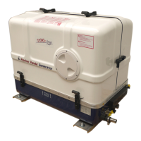
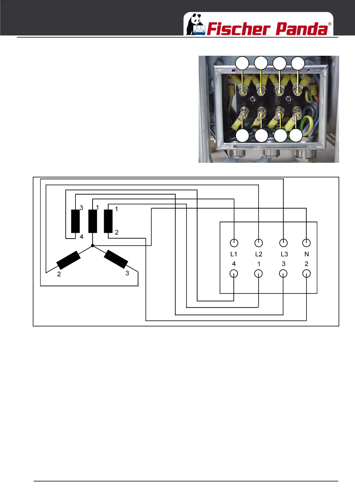
Fig. 8.6.5-9: Generator power terminal box DVSGenerator Power Terminal Box DVS - 120 V + 240 V /
60 Hz
In these terminal box there are the electrical connection
points for the AC generator. Here is also the bridge for the
protective grounding of the generator. The cover may only be
removed, if it is guaranteed that the generator cannot be
inadvertently started.
representative picture
Fig. 8.6.5-10: Wiring diagram DVS - 120 V + 240 V / 60 Hz