User’s manual FlexGain Plex, V2
Version 1.3 92 from 99
Each of four unit interfaces has two input sensors and two actuating mechanisms
(switches).
Each sensor detects the grounding of a negative M60V potential performed by a
coupled device.
Each switch controls the negative potential fed from the coupled device. In the active
mode, the switch grounds the potential to the GATS line (Ground PBX) while it does not
change it in the passive mode.
The unit provides coupling of the device with external equipment with E&M interfaces
of types 3 and 5.
Внимание! Категорически запрещается подавать положительный относительно
земли устройства или линии GATS потенциал на входные и выходные линии
интерфейса. Это может привести к выходу из строя как мультиплексора, так и
сопрягаемого с ним оборудования!
Е&M signaling.
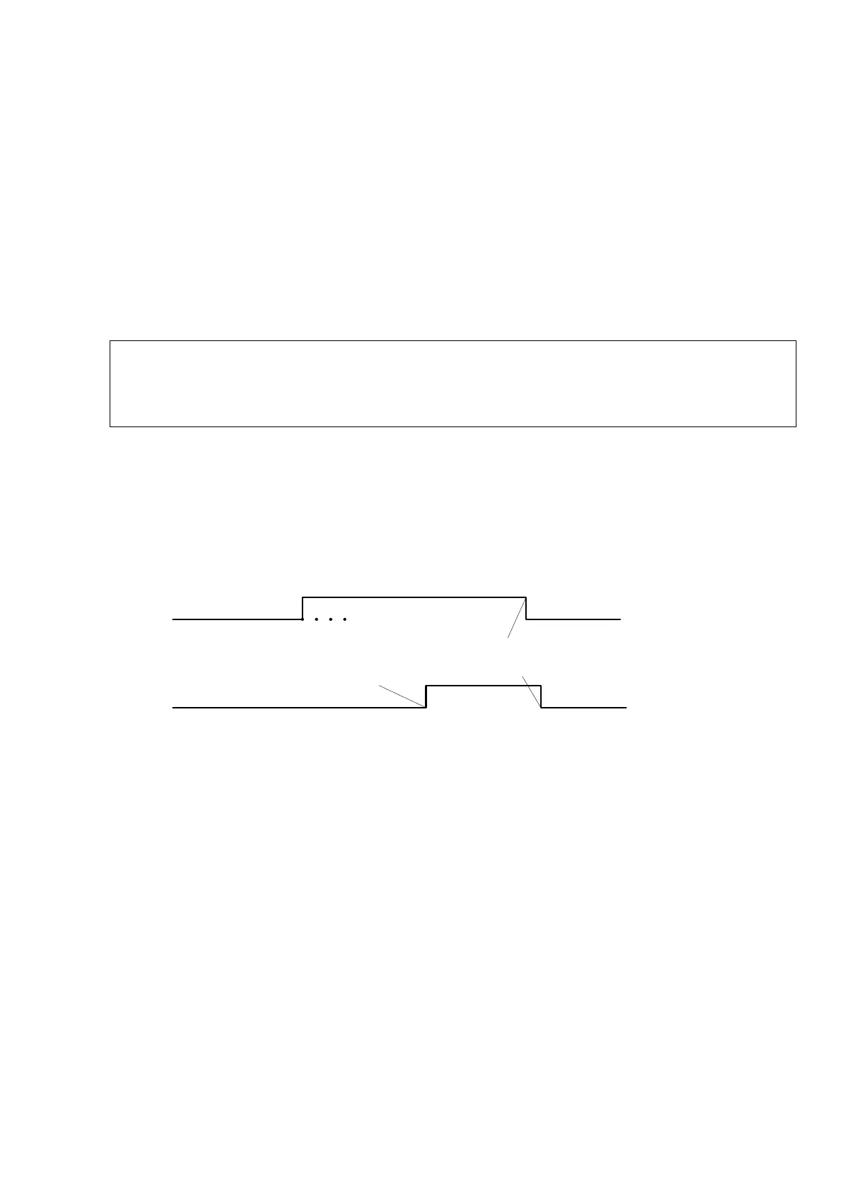
The exchange protocol during the connection establishing and breaking between the
multiplexer and the device connected to it is presented in Fig. 17.
Figure 14. Exchange protocol over the E&M interface.
In Fig. 17, the calling party is the party, which initiated the exchange, while the called
party is the device, which supports this exchange.
In this version of the software, the state of input signals of the interface of a local unit
is transmitted in bit a and b of the signaling TS and is repeated by output signals of the
interface of a remote unit without any additional time delays.
Single- and multi-frequency signaling, which uses the voice channel are transmitted
transparently without any delays and interpretation.
The operation modes of the device are set with the help of jumpers, whose position
of the printed circuit board of the unit is presented in Fig. 18.
In Fig. 19 and Table 19 and 20, «OPEN» means an open state of the jumper, while
«CLOSE» means closed state of the jumper. The configuration of the interface for two- and
four-wire operation modes is set by jumpers JP2, JP4, JP6, J8 и JP9, JP10, JP11, JP12.
The configuration parameters are presented in the Table below.
Calling party
Called party
Dialing
E or M
M or E
Reply
Clear
Clear
Talk
Busy
Idle state
Busy
Idle state