User’s manual FlexGain Plex, V2
Version 1.3 93 from 99
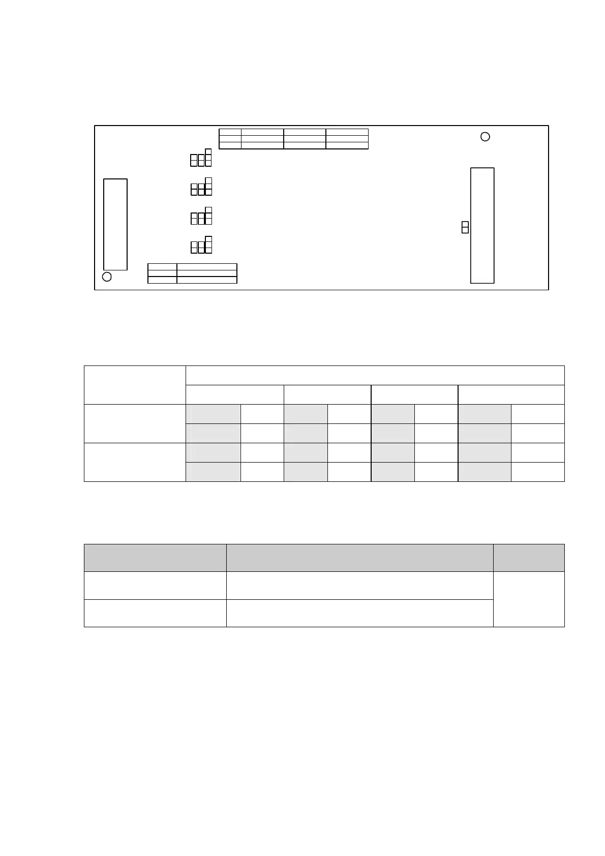
Figure 15. Position of jumpers on the E&M unit.
Table 19. Position of jumpers in different operation modes.
Interface
Operation mode
1 (5) 2(6) 3(7) 4(8)
JP2 2-3 JP4 2-3 JP6 2-3 JP8 2-3
Two-wire mode
JP9 CLOSE JP10 CLOSE JP11 CLOSE JP12 CLOSE
JP2 1-2 JP4 1-2 JP6 1-2 JP8 1-2
Four-wire mode
JP9 OPEN JP10 OPEN JP11 OPEN JP12 OPEN
Jumper JP1, JP3, JP5, J7, whose parameters are presented in Table 20, are used
to change the receive-signal gain.
Table 20. Change of the receive-signal gain.
JP1, JP3, JP5, JP7 Four-wire mode
Two-wire
mode
OPEN
Nominal level at the input = - 13.0 dB
Nominal level at the output = + 4.0 dB
CLOSE
Nominal level at the input = +6.0 dB
Nominal level at the output = +3.0 dB
CLOSE
Some printed circuit boards have a JP13 jumper, which is used by the manufacturer
for testing the equipment.
The two-wire operation mode of the FlexGain Plex, V2 is optional.
The Table presented below shows the correspondence of some values configured
with the help of the <PORT Px NRT> command to the signal level in absolute and arbitrary
units.
3
2
1
JP7
JP12
JP8
3
2
1
JP5
JP11
JP6
3
2
1
JP3
JP10
JP4
3
2
1
JP1
JP9
JP2
JP13
DISABLE
ENABLE
CLOSE
OPEN
JP14 JP15 JP16 JP17
CLOSE
OPEN
J1 J3 J5 J7
2 WIRE
4 WIRE
2 - 3
1 - 2
J2 J4 J6 J8
CLOSE
OPEN
J9 J10 J11 J12