7 Connection
PIOX R721 7.2 Power supply
37
UMPIOX_F72xV1-3EN, 2021-09-01
7.2.1 Cable connection
Transmitter with stainless steel housing
• Remove the blind plug to connect the cable to the transmitter.
• Prepare the cable with a cable gland. The used cable has to have a wire cross-section of 0.25…2.5 mm². The outer
diameter of the cable where the ferrite nut is placed may not exceed 7.6 mm.
• Push the cable through the cap nut, compression part, basic part and the sealing ring (sealing ring: only for cable gland
M20, not for cable gland 1/2 NPS).
• Insert the cable into the housing of the transmitter.
• Fix the cable gland by screwing the cap nut onto the basic part.
• Fix the sensor cable by tightening the cable gland with the ferrite nut.
• Connect the cable to the terminals of the transmitter.
Tab. 7.4: Terminal assignment
terminal connection AC connection DC
PE earth earth
N(-) neutral -
L(+) phase 100...230 V AC, 50...60 Hz +
fuse 1 A, time-lag 1.6 A, time-lag
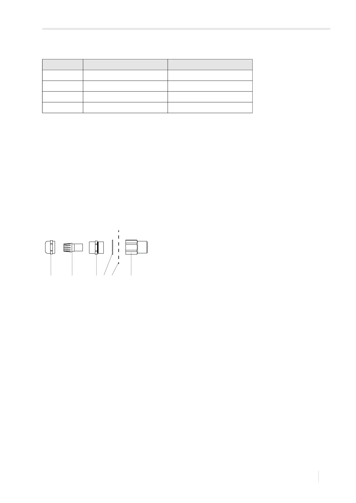
Fig. 7.7: Cable gland for stainless steel housing
1 – cap nut
2 – compression part
3 – basic part
4 – sealing ring (only for cable gland M20, not for cable gland 1/2 NPS)
5 – housing wall
6 – ferrite nut
21 3 4 5 6