7 Connection
PIOX R721 7.4 Inputs
41
UMPIOX_F72xV1-3EN, 2021-09-01
7.4 Inputs
7.4.1 Current input
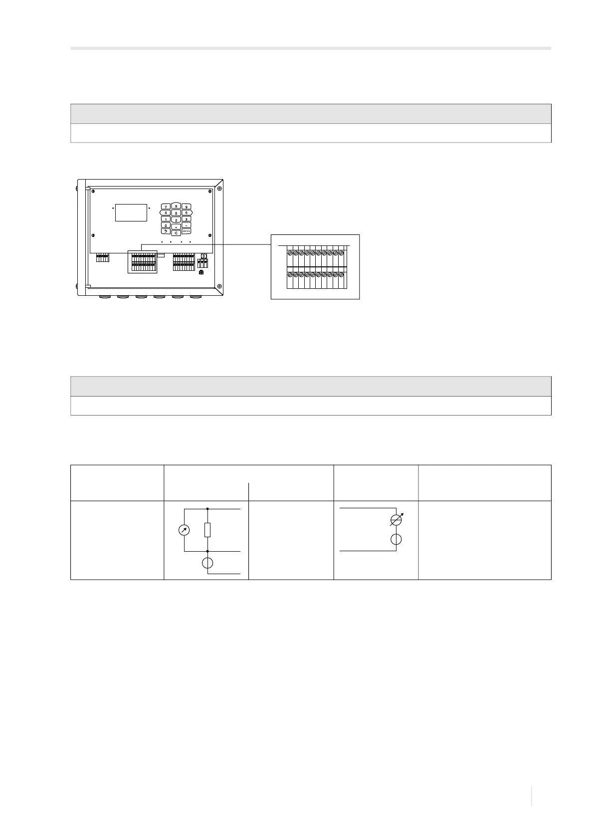
An active (self-powered) or a passive (external powered) current source can be connected to the current inputs of the
transmitter.
Connection of an active current source
For the connection of the input cable to the transmitter see section 7.2.1, Fig. 7.10 and Tab. 7.6.
If the polarity of the current source is inversed, only the sign of the measured current will change.
Important!
The max. permissible voltage between the inputs and against PE is 60 V DC (permanent).
Fig. 7.10: Connection of the transmitter inputs
Important!
The terminals Txa and Txb must not be connected.
Tab. 7.6: Connection of an active current source
input transmitter external circuit remark
internal circuit connection
current input max. permanent overcurrent:
100 mA
A
B
SNAP
DISP
DISP
MODEFAST
MUX
NEXT
Q
ON
Q+Q-
3x Q
OFF
LAN
USB
A+
B-
P1+
P2+
P3+
P4+
P5a
P6a
P7a
S
S
P1-
P2-
P3-
P4-
P5b
P6b
P7b
KL7KL8
KL9KL10
KL4
T1A
T1B
S1
T2A
T2B
T3A
T3B
S3
T4B
T4A
T1a
T1b
S1
T2a
T2b
T3a
T3b
S3
T4b
T4a
N(-)
PE
L(+)
V+
V-
A+
B-
KL7KL8
T1A
T1B
S1
T2A
T2B
T3A
T3B
S3
T4B
T4A
T1a
T1b
S1
T2a
T2b
T3a
T3b
S3
T4b
T4a
V
R
int
+
-
TxA
Txb
Txb (not connected)
+
-
-
+