17 Event trigger
17.1 Apparent switching delay PIOX R721
2021-09-01, UMPIOX_F72xV1-3EN
88
17.1 Apparent switching delay
The measured values will be displayed rounded according to the set number of decimal places. The limits, however, will
be compared to the non-rounded measured values. This might cause an apparent switching delay when the measured
value changes marginally (less than the displayed decimal places). In this case, the switching accuracy of the event
trigger is higher than the accuracy of the display.
17.2 Reset and initialization of the event trigger
After an initialization of the transmitter all event triggers are deactivated.
• Press 3 times C during the measurement to set all event triggers to the idle state.
Event triggers whose switching condition is still met will be activated again after 1 s. This function is used to reset event
trigger of the type HOLD if the switching condition is no longer met.
If a measurement is stopped, all event triggers will be de-energized, independently of the programmed idle state.
17.3 Event trigger during the measurement
An event trigger with the switching condition MAX (x>limit), MIN (x<limit), Within range or Out of range will
be updated max. once per second to avoid a constant switching of the event trigger (i.e. fluctuation of the measured
values around the value of the switching condition).
An event trigger with switching condition ERR (x=fail) will be activated during a measurement failure.
An event trigger of the type Non-hold will be activated if the switching condition is met. It will be deactivated if the
switching condition is no longer met. The alarm remains activated for at least 1 s even if the switching condition is met for
a shorter period of time.
An event trigger of the type Hold will be activated if the switching condition is met. It remains activated even if the
switching condition is no longer true.
An event trigger of the type Hold for a while will be activated if the switching condition is met. In the menu item Hold
interval the time is defined when deactivation takes place.
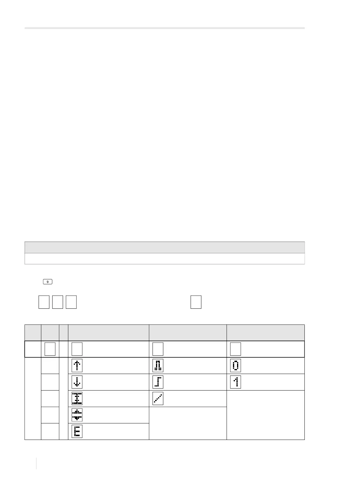
17.4 Status display of the event trigger
The state of the event triggers is displayed during the measurement.
• Press to scroll through the second line from below until the event trigger status is displayed.
The status display of the event triggers is structured as follows.
Rx = with X being the number of the event trigger and a pictogram according to Tab. 17.3.
Notice!
There is no visual or acoustic indication of event trigger switching.
Tab. 17.3: Pictograms for the status display of the event triggers
no. Function
(switching condition)
Type
(holding behavior)
current state
R =
1 MAX (x>limit) Non-hold not activated (false state)
2 MIN (x<limit) Hold activated (true state)
3 Within range Hold for a while
4 Out of range
ERR (x=fail)