7 Connection
7.3 Outputs PIOX R721
2021-09-01, UMPIOX_F72xV1-3EN
38
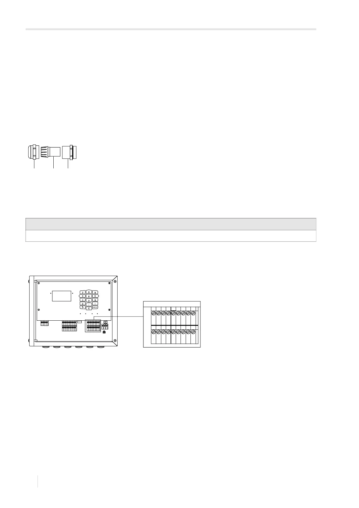
Transmitter with aluminum housing
• Remove the blind plug to connect the cable to the transmitter.
• Prepare the cable with a cable gland.
The used cable has to have a wire cross-section of 0.25…2.5 mm².
• Push the cable through the cap nut, compression part and basic part of the cable gland.
• Insert the cable into the housing of the transmitter.
• Screw the sealing ring side of the basic part into the transmitter housing.
• Fix the cable gland by screwing the cap nut onto the basic part.
• Connect the cable to the terminals of the transmitter.
7.3 Outputs
• Connect the output cable to the transmitter (see 7.2.1, Fig. 7.9 and Tab. 7.5).
Fig. 7.8: Cable gland for aluminum housing
1 – cap nut
2 – compression part
3 – basic part
Important!
The max. permissible voltage between the outputs and against PE is 60 V DC (permanent).
Fig. 7.9: Connection of the outputs on the transmitter
21 3
A
B
SNAP
DISP
DISP
MODEFAST
MUX
NEXT
Q
ON
Q+Q-
3x Q
OFF
LAN
USB
A+
B-
P1+
P2+
P3+
P4+
P5a
P6a
P7a
S
S
P1-
P2-
P3-
P4-
P5b
P6b
P7b
KL7KL8
KL9KL10
KL4
T1A
T1B
S1
T2A
T2B
T3A
T3B
S3
T4B
T4A
T1a
T1b
S1
T2a
T2b
T3a
T3b
S3
T4b
T4a
N(-)
PE
L(+)
V+
V-
A+
B-
A+
B
P1+
P2+
P3+
P4+
P5a
P6a
P7a
S
S
P1-
P2-
P3-
P4-
P5b
P6b
P7b
KL9KL10
-