PIOX S70x 7 Connection
68 UMPIOX_S7V4-6-3EN, 2018-10-10
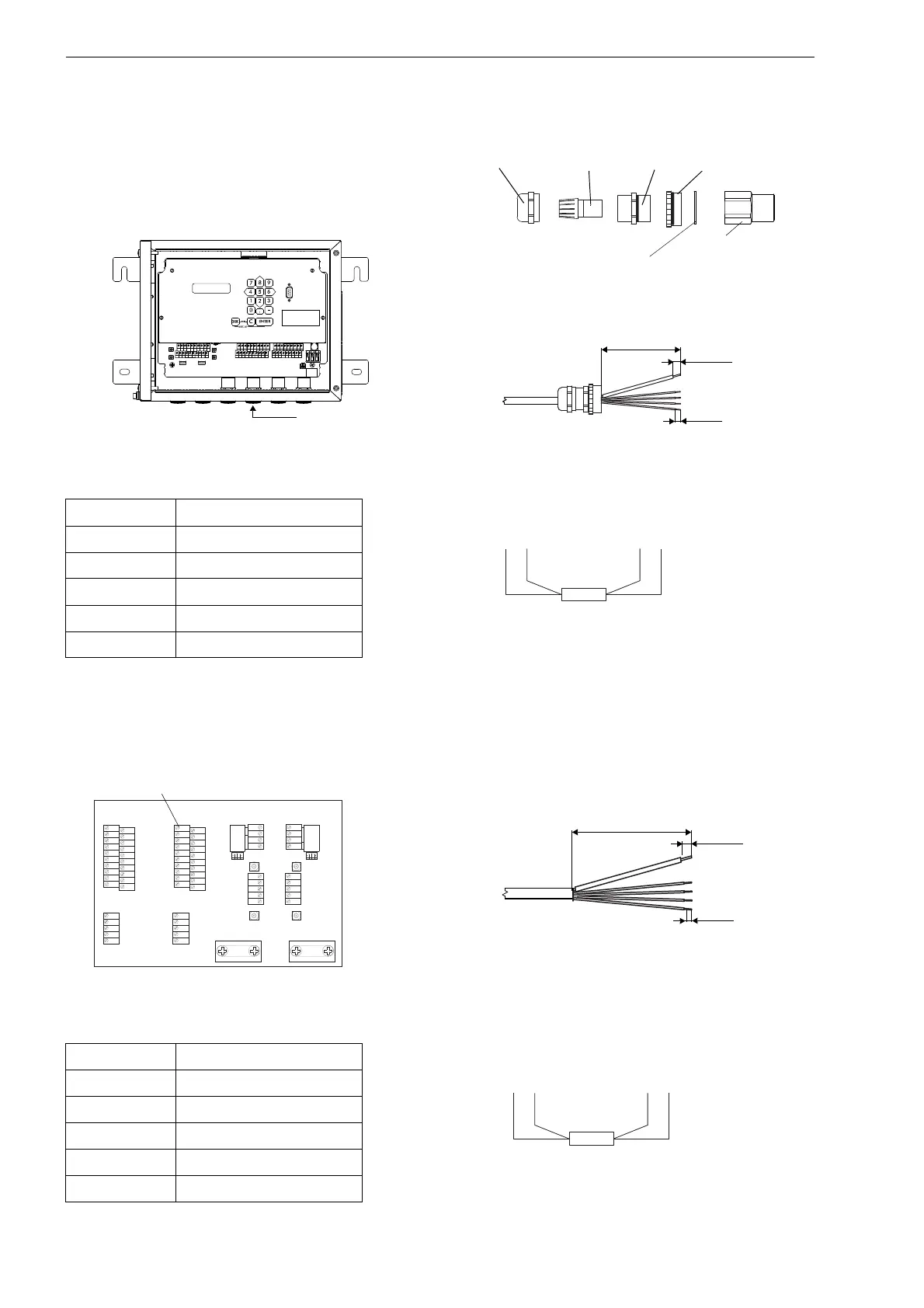
PIOX S709
• Prepare the cable of the temperature probe (see Fig. 7.30).
• Connect the temperature probe to the terminals of the transmitter (see Fig. 7.3, Fig. 7.29 and Tab. 7.14).
Fig. 7.26: Transmitter PIOX S705 Fig. 7.27: Cable gland and preparation
Tab. 7.13: Terminal assignment of the transmitter
terminal temperature probe
Fig. 7.28: Temperature probe
T1a...T4a red
T1A...T4A red/blue
T1b...T4b white/blue
T1B...T4B white
S1...S4 shield
Fig. 7.29: Transmitter PIOX S709 Fig. 7.30: Preparation of the cable
Tab. 7.14: Terminal assignment of the transmitter
terminal temperature probe
Fig. 7.31: Temperature probe
T1a...T4a red
T1A...T4A red/blue
T1b...T4b white/blue
T1B...T4B white
S1...S4 shield
AVS
AV
AGN
ARS
X2
X_BV
X_BR
X_AV
X_AR
X1
AR
BVS
BV
BGN BRS
BR
SA1 SA2 SA3 SA4 SB1
SB2
SB3
SB4
T1a T1b
S2 T2a
T3a
T3b
S4
T4a
T2b
T4b
T1A T1B
S1 T2A
T3A
T3B
S3
T4A
T2B
T4B
A+
B-
P1+ P2+
P4+
P5a
P6a P7a
P3+
101
103
P1- P2-
P4-
P5b
P6b
P7b
P3-
PE
N(-)
L(+)
cap nut
compression
part
basic part
reducer
ferrite nut
sealing ring:
only for cable gland M20,
not for cable gland 1/2 NPS
redred/blue white/blue white
K L 7
K L 5
K L 3
K L 1
X 7
K L 4K L 2
X 6 A V
X 8 B V
X 6 A R X 8 B R
X 5
BA
K L 6
K L 8
C H A N N E L
S A 3
S A 1
S A 2
S A 4
S B 3
S B 1
S B 2
S B 4
A V S
A V
A R S
A G N
A R
B V S
B V
B R S
B G N
B R
4 A +
4 B -
4 2
4 3
4 1
L +
L -
N
L 1
P E
P 6 a
P 7 a
P 7 +
P 5 a
P 6 +
P 2 +
P 5 +
P 1 +
P 3 +
P 4 +
P 6 b
P 7 b
P 7 -
P 5 b
P 6 -
P 2 -
P 5 -
P 1 -
P 3 -
P 4 -
T 4 A
T 4 B
T 3 B
S 3
T 3 A
T 1 B
T 2 B
T 1 A
S 1
T 2 A
T 4 a
T 4 b
T 3 b
S 4
T 3 a
T 1 b
T 2 b
T 1 a
S 2
T 2 a
redred/blue white/blue white

 Loading...


